Hello,
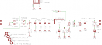
I designed a pcb for a regulated supply using LM317/LM338/LT108x.
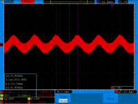
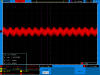
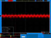
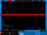
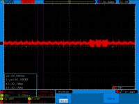
So I made the boards and populated them and then made some measurements using my (also) newly made TDA7297 amp. This chip has a current limit of 2A. When I run the chip past 1A I get some oscillations on the regulator board. Looks like a doubling of the amp's test frequency. The lower the frequency the larger the noise. I made all these screenshots at the same volume. You can deduct the test frequency from the frequency of the oscillation. I made the measurement on the output of the PS board. I also get something similar from another PS board used with a ta2020 amp, but the overall effect is smaller. The tda PS uses a LT1083 (or 84, can't remember now) regulator and the ta2020 amp uses a lm338 regulator.
I attached the schematic used for the power supply.
Also I had to shut off all cfl lights, removed all smps from sockets and shut down computer. Basically it was only the amp and oscilloscope running in the whole house")
There are about 20cm of cable between PS and TDA board. And basically nothing is grounded, only the transformer. And there is no case at the moment
So is this normal for this type of power supply? Forgot to mention that I'm running the output of the PS at 16.5VDC. As I go past 1A I start to see the test sine wave (doubled in freqency) on the output of the PS.
The regulating chip is well cooled by a decent heatsink, it just stays warm. I modified the schematic to reflect the exact values of the components used on the PS board.
PS.
Yes, I'm using two paralleled resistors for R2 so I can set a more precise output voltage. It's staying there, yes, I like it that way Unless that's the culprit, which I don't think so.
pps.
The output capacitor is made of 2x 10uF tantalum capacitors soldered together. I only had a 68uF R2 bypass capacitor and as per application I adapted the output capacitor.
ppppppppppps
the ta2020 PS board uses a LM338 regulator with different R2 bypass capacitor / output capacitor combo, and still shows something similar. I know LT108x are prone to oscillation if the output capacitor is not in spec with the datasheet, or low esr. Also the TDA board has diodes on power input as I'm splitting into two power rails for the amplifier chip. On the ta2020 board power goes directly to some low esr FM caps.
I noticed that if I add a whatever value capacitor at about half the distance between the PS and the amp this effect decreases.
I designed a pcb for a regulated supply using LM317/LM338/LT108x.
So I made the boards and populated them and then made some measurements using my (also) newly made TDA7297 amp. This chip has a current limit of 2A. When I run the chip past 1A I get some oscillations on the regulator board. Looks like a doubling of the amp's test frequency. The lower the frequency the larger the noise. I made all these screenshots at the same volume. You can deduct the test frequency from the frequency of the oscillation. I made the measurement on the output of the PS board. I also get something similar from another PS board used with a ta2020 amp, but the overall effect is smaller. The tda PS uses a LT1083 (or 84, can't remember now) regulator and the ta2020 amp uses a lm338 regulator.
I attached the schematic used for the power supply.
Also I had to shut off all cfl lights, removed all smps from sockets and shut down computer. Basically it was only the amp and oscilloscope running in the whole house
There are about 20cm of cable between PS and TDA board. And basically nothing is grounded, only the transformer. And there is no case at the moment
So is this normal for this type of power supply? Forgot to mention that I'm running the output of the PS at 16.5VDC. As I go past 1A I start to see the test sine wave (doubled in freqency) on the output of the PS.
The regulating chip is well cooled by a decent heatsink, it just stays warm. I modified the schematic to reflect the exact values of the components used on the PS board.
PS.
Yes, I'm using two paralleled resistors for R2 so I can set a more precise output voltage. It's staying there, yes, I like it that way
Unless that's the culprit, which I don't think so.pps.
The output capacitor is made of 2x 10uF tantalum capacitors soldered together. I only had a 68uF R2 bypass capacitor and as per application I adapted the output capacitor.
ppppppppppps
the ta2020 PS board uses a LM338 regulator with different R2 bypass capacitor / output capacitor combo, and still shows something similar. I know LT108x are prone to oscillation if the output capacitor is not in spec with the datasheet, or low esr. Also the TDA board has diodes on power input as I'm splitting into two power rails for the amplifier chip. On the ta2020 board power goes directly to some low esr FM caps.
I noticed that if I add a whatever value capacitor at about half the distance between the PS and the amp this effect decreases.
Attachments
-
 reg.png13.6 KB · Views: 272
 -
 20140304_323328.png22.8 KB · Views: 279
 -
 20140304_323439.png24.2 KB · Views: 269
 -
 20140304_323540.png26.4 KB · Views: 267
 -
 20140304_323620.png26.6 KB · Views: 262
 -
 20140304_323720.png24.8 KB · Views: 49
 -
 20140304_323756.png23.4 KB · Views: 48
 -
 20140304_323856.png23.6 KB · Views: 65
Last edited:
I think the issue stems from the regulator output impedance.
I made some pretty tough rail PSs (4-5A) based on the LM723 and high gain high current pass devices (darlington), and with a high capacitance bank AFTER the reg/pass device (22000uf per rail). Voltage value is rock steady no matter what. To take care of the pass devices I have to turn on the PS through a soft start circuit. It's been working like a charm for a few months and I turn it on daily.
My advice here is try installing high gain darlington pass devices even if the required current is within the regulator capabilities. A really big output capacitor (10000uf or more per rail) will turn your PS super steady but you will need a soft start to turn it on.
Which is the capacitance value of the input bank?
Try some resistance in series with tantals (1R or less).
There is already, 47uF in series with 0.47R.
try testing the regulator alone with dummy loads 1st.
check DC stuff 1st , ensure Vin to Vout under max load is at least 3 VDC
make sure it works stable and heat sinking is good enough.
testing 2 new things at once by analyzing AC waveforms , is like trying to run before you can walk
back to basics gents
check DC stuff 1st , ensure Vin to Vout under max load is at least 3 VDC
make sure it works stable and heat sinking is good enough.
testing 2 new things at once by analyzing AC waveforms , is like trying to run before you can walk
back to basics gents
Last edited:
Trileru, from your description I get the impression that beyond 1A the stability margins of the regulator are exceeded.
You can solve this in several ways:
Or you can apply a small series resistor ( .2 a .3 Ohms) and some 10 to 20 mF on the output line. This will give less load regulation, but better ripple and noise performance.
You can solve this in several ways:
Try some resistance in series with tantals (1R or less).
Or you can apply a small series resistor ( .2 a .3 Ohms) and some 10 to 20 mF on the output line. This will give less load regulation, but better ripple and noise performance.
I suggest (but don't take me too seriously
Best regards.
Actually I've made the test before connecting the snubber. It made no difference, looked the same before/after
A board layout would be very helpful.
Attachments
Last edited:
Trileru, from your description I get the impression that beyond 1A the stability margins of the regulator are exceeded.
You can solve this in several ways:
Or you can apply a small series resistor ( .2 a .3 Ohms) and some 10 to 20 mF on the output line. This will give less load regulation, but better ripple and noise performance.
I just mentioned that there is a 0.47R resistor and 47uF capacitor in series on the output. It made no difference with/without.
After I make the test with more resistance on the output I will post the result.
Just some thoughts. Might this just be the normal operating characteristics of the 338? The frequency is a doubling of the signal used for testing. Equal amounts of current is drawn for both the up-going and down-going part of the sinewave. That's the doubling. Edit: You can check this by measuring the input signal too and check if the vallies of the PSU's output correspond with the peak-peaks from the sinewave.
The LM338 itself has a typical load regulation of 0.3% over the full temperature range (1% max). 48mV is 0.29% of the 16.5V output. That's within spec. Heat is a factor here. Your heatsink seems rather small. I don't know the input voltage, but let's assume it's a 7.5K/W type heatsink + the TO220's thermal resistance (1K/W) + the goop/silicone, that's another 0.5K/W, making a total of 9K/W. If let's say the LM338 has to drop 5 volts at 2 amps, that's 10W. Raising the temperature 90K above ambient, usually 25C, making 115C!! So the LM338 becomes hot! And line regulation gets worse.
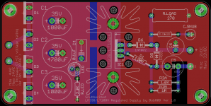
Concerning the PCB layout, there's a lot of possibility for ground loops and high current paths going past sensitive circuitry. The effects become increasingly worse when more current is drawn. Ground planes are not an easy one-for-all solution. Currents flow through the ground-plane and sometimes through (sensitive) parts where you don't want it to. I learned that the hard way not long ago. Be mindful with component placing. For example, the diodes are not critical for normal operation, so their spot would be better suited for the bias network.
So things to improve and perhaps increase the line regulation? You could increase the output capacitance, making shure the stability is maintained. Better cooling? Try force-cooling the heatsink (fan) and see if it improves. Maybe shuffle the board layout a bit, keeping ground currents in mind. But for the most part, I believe this is just the rail showing a normal changing load.
Oh and why the 270ohm load resistor? The LM338 minimum load is 3.5mA (10mA max), which is easily drawn by the bias network alone.
The LM338 itself has a typical load regulation of 0.3% over the full temperature range (1% max). 48mV is 0.29% of the 16.5V output. That's within spec. Heat is a factor here. Your heatsink seems rather small. I don't know the input voltage, but let's assume it's a 7.5K/W type heatsink + the TO220's thermal resistance (1K/W) + the goop/silicone, that's another 0.5K/W, making a total of 9K/W. If let's say the LM338 has to drop 5 volts at 2 amps, that's 10W. Raising the temperature 90K above ambient, usually 25C, making 115C!! So the LM338 becomes hot! And line regulation gets worse.
Concerning the PCB layout, there's a lot of possibility for ground loops and high current paths going past sensitive circuitry. The effects become increasingly worse when more current is drawn. Ground planes are not an easy one-for-all solution. Currents flow through the ground-plane and sometimes through (sensitive) parts where you don't want it to. I learned that the hard way not long ago. Be mindful with component placing. For example, the diodes are not critical for normal operation, so their spot would be better suited for the bias network.
So things to improve and perhaps increase the line regulation? You could increase the output capacitance, making shure the stability is maintained. Better cooling? Try force-cooling the heatsink (fan) and see if it improves. Maybe shuffle the board layout a bit, keeping ground currents in mind. But for the most part, I believe this is just the rail showing a normal changing load.
Oh and why the 270ohm load resistor? The LM338 minimum load is 3.5mA (10mA max), which is easily drawn by the bias network alone.
Last edited:
Thank you for the info.
I'm actually using a LT1084 with the TDA amp. And my heatsink has a 4.5K/W rating. Rectified voltage is 22.5VDC, so -1.5VDC for the regulator -16.5VDC output leaves 4.5VDC on the regulator to be burned. At 2A that's 9W. At 1A it's only half of that, so with 6K/W rating that's only 27 degrees + 25 room temp. So 52 or even 55 degrees C is not much. At full 2A it would theoretically go up to 79-80 degrees. No issues with heating. I'm more concerned with the rectifying diodes as they drop 4V at 2A, so that's 2W per diode. I can't test for more than a few seconds as I don't have a heatsink for them and I won't be bothered to make one as they will probably never need it. I don't think that they will ever see 1W continuously each. But my layout permits such a heatsink for those diodes if need be anyway
I also separated the ground planes to keep the currents from going crazy. There's a split in the middle with only a thin portion to tie the rectifying part from the regulated part. And also I separated C5 from the ground plane, only to join at the output.
For the minimum current I was aiming for about 50mA just to keep the regulator happy (lt108x is around 5-10mA minimum current draw). And I didn't have any 330ohm resistor in a larger package so I used what I had at hand. No worries, 60mA is ok. That's about 1W and I put a 5W resistor.
LT1084 line regulation is about 0.035% for Vin-Vout = 5V, and I have about 6V. And line regulation is guaranteed for the whole power dissipation of the device, and for LT1084 for Vin-Vout=5V the current limit is of 6.5A, or about 30W.
quote from the datasheet:
Note 3: Line and load regulation are guaranteed up to the maximum power
dissipation (60W for the LT1083, 45W for the LT1084 (K, P), 30W for the
LT1084 (T) and 30W for the LT1085). Power dissipation is determined by
the input/output differential and the output current. Guaranteed maximum
power dissipation will not be available over the full input/output voltage
range.
So 48mV or 0.29% of output is an order of magnitude worse. Although it is stated that worst case scenario is 0.2% but typically 0.035-0.05%.
And I see no change between cold start and later on while testing.
I made the measurements with ground on C5 negative leg and signal on C6 positive leg.
P.S.
This is the heatsink that I'm using:
http://www.tme.eu/en/details/sk129-63sts/radiators/fischer-elektronik/#
That is not how I interpreted the schematic you provided. The way I interpreted your schematic is that the resistor/capacitor (.47R/47uF) is in parallel to the load.I just mentioned that there is a 0.47R resistor and 47uF capacitor in series on the output. It made no difference with/without.
After I make the test with more resistance on the output I will post the result.
What I tried to suggest is a series resistor (.2/3 Ohms) following the regulator with a large capacitor shunting the load. I did not mean the .47R/47uF snubber
Ah ok, I missed the part for LT1084 vs. LM338 . However, we're talking load regulation (made the typo myself just now). Load regulation for the 1084 is between 0.2% and 0.4% @ 25C. The 0.015 is line regulation; how well it withstands changes in input voltage. So your 0.29% is well within spec.
Concerning the diodes. They don't have a sinusoidal current through them, but the loading peaks produced by the caps instead. Most of the time, the datasheet has a separate, usually higher, current rating for this.
The temperature resistance given by LT is a very realistic. Worst case scenario is 2.7K/W. I'm not saying the 1084 is getting too hot, just that it all adds up. At 1 amp, we could potentially see a junction temp of 60C. If the PSU is put inside a small enclosure, ambient will rise to etc. etc. Again, load regulation gets worse with temperature.
Check the current path of the adjust pin cap and bias network for example. They're tied to the common output pin. That's a high current point!
. However, we're talking load regulation (made the typo myself just now). Load regulation for the 1084 is between 0.2% and 0.4% @ 25C. The 0.015 is line regulation; how well it withstands changes in input voltage. So your 0.29% is well within spec. Concerning the diodes. They don't have a sinusoidal current through them, but the loading peaks produced by the caps instead. Most of the time, the datasheet has a separate, usually higher, current rating for this.
The temperature resistance given by LT is a very realistic. Worst case scenario is 2.7K/W. I'm not saying the 1084 is getting too hot, just that it all adds up. At 1 amp, we could potentially see a junction temp of 60C. If the PSU is put inside a small enclosure, ambient will rise to etc. etc. Again, load regulation gets worse with temperature.
Check the current path of the adjust pin cap and bias network for example. They're tied to the common output pin. That's a high current point!
can you show the PCB reverse side as well. There should be a split on the ground side mirroring the top side. otherwise two overlapping ground planes form a pretty good coupling capacitor, contaminating the output ground with fast charging pulses.
big symptom > doubling on the AC signal points to diodes. Test with a big enough static output and load look for 100 Hz stuff on the outputs. Remember common mode ripple and noise is untouched by the regulator. My experience has been using ground planes are nothing but trouble for DC power and/ or audio power amps. DC headroom looks OK I guess, measurements preferred over load analysis. how about AC waveforms with a dummy load applied?
big symptom > doubling on the AC signal points to diodes. Test with a big enough static output and load look for 100 Hz stuff on the outputs. Remember common mode ripple and noise is untouched by the regulator. My experience has been using ground planes are nothing but trouble for DC power and/ or audio power amps. DC headroom looks OK I guess, measurements preferred over load analysis. how about AC waveforms with a dummy load applied?
can you show the PCB reverse side as well. There should be a split on the ground side mirroring the top side. otherwise two overlapping ground planes form a pretty good coupling capacitor, contaminating the output ground with fast charging pulses.
Red is top side and is ground, and bottom is blue and is power plane and stops at the regulator. I don't know how to show the bottom side as all the information is already in that picture
Later on, after I replace the oil in my bike and give it a nice wash I will add some more capacitance on the output of the board and make the tests. I have a couple of 8ohm 100W resistors.Red is top side and is ground, and bottom is blue and is power plane and stops at the regulator. I don't know how to show the bottom side as all the information is already in that picture
Hi, as I stated earler in the thread I think you will benefit from extra capacitance (large value) on the output side if you install a high current and gain device like a darlington transistor. That way you will unload the regulator transfering the job to the pass device. It will also take care of the large capacitance charging current and keep the voltage value steady.
- Status
- This old topic is closed. If you want to reopen this topic, contact a moderator using the "Report Post" button.
- Home
- Amplifiers
- Power Supplies
- regulated supply oscillation or whatever that is