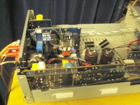
I know i´m a perfect alien in this forum, and in electronics in general..., but i would really appreciate if someone could shed some light on the TEAC capacitors upgradability for me. There is one 35V 1000uF (power decoupling?) on the chip board next to the inductors that could/should be replaced by a 50V one but how reasonable would be an increase in capacitance,30%, 50%, 150%?
Then there are the two 2200uF 50V (one for each board?) on the power supply board, are these power supply filtering/smoothing caps? What about the large one(400V 220uF) near the transformer, is this the oneTripathdude replaced with a Jensen?
Help, i´m lost here! I just want to improve slightly the stock unit by replacing some parts (the center board is already gone) without spending too much and have some fun in the process.
Thank you.
I appreciate you help Risperdal, i´m also a newbie (perhaps not even that...) and since i don´t have any schematics (it would be nice if someone here at diyAudio could email me some) or any trainning in electronics my mods are mainly based on empirical grounds and googling.
Despite euro scarcity around here i managed to order some parts and i my intents are:
- change the 35V power decoupling cap for 50v better quality one
- C808/9 will remain electrolytics but hopefully of better quality also
- the 2200 uF PSU filter cap will be replaced by a 10000 uF low ESR one
- some other caps will perhaps also be replaced a i thought of improving the tripath heatsink too
What do you think of 10000uF cap, will it be overkill? Are those two 2200uF really the PSU filter caps, one for each board? I´m might bypass it with small PS or PP capacitor.
Stepped attenuator would be nice but I´m afraid is too expensive.
Regarding the WF82 to speaker out hardwiring, have you done it directly to the speakers binding posts, what kind of wire? Wil this not introduce noticeable RF polution?
Thanks.
I`ve been evaluating my first mods over the last weeks and I belive it´s safe to say that just by changing the 2200 cap for 10000 panasonic low ESR and the little caps on the "volume pots" (I`m not getting rid of these just yet) made some significant improvements in sound.
First change was in the PSU board with the 10000uF cap bypassed with a 0,022uf Polystyrene: powerfull but cahotic bass and very strange treble. Not enough capacitance on the bypass? Too much inductance due to (axial) capacitor leads ? I gave it some hours of music for a few days to settle in, meanwhile I changed the gain caps and the improvement was obvious (mainly soundstage and detail) but the overall bad result from the bypassed 10000 prevailed, so I decided to get rid of the bypass and put the large cap directly on the board and this way is sounding much better: punching tight bass and sweet treble, voices are really appearing in the room now. Nex mod: the 35V 1000uf for a 50V one, I`m afraid that increasing capacitance can bring too much bass though.
First change was in the PSU board with the 10000uF cap bypassed with a 0,022uf Polystyrene: powerfull but cahotic bass and very strange treble. Not enough capacitance on the bypass? Too much inductance due to (axial) capacitor leads ? I gave it some hours of music for a few days to settle in, meanwhile I changed the gain caps and the improvement was obvious (mainly soundstage and detail) but the overall bad result from the bypassed 10000 prevailed, so I decided to get rid of the bypass and put the large cap directly on the board and this way is sounding much better: punching tight bass and sweet treble, voices are really appearing in the room now. Nex mod: the 35V 1000uf for a 50V one, I`m afraid that increasing capacitance can bring too much bass though.
hello, anyone know what the 2 x 2.2uf 50v & one 16v 100uf on the amp board do? any benefit from upgrading them ? thanks
Hello Dynoport, I believe the 2 x 2.2uf 50V would be the input caps C808/C809 like Risperdall wrote but I'm no expert and I can't confirm this right now, you can check if they are C808/9 though.
I think i might have a Tripath scheme somewhere and this might help if you can read it (unlike me...).
I´ll get back to this as soon as I can for I know how difficult is to get someone to help on this amp/chip nowadays.
thanks for the reply, I thought the input caps were C100 C101 on the 'volume' board?

I'm so sorry I haven't been able to help you sooner but I couldn't find the scheme yet, I suspect it's on another PC that broke down recently... I've been willing to back up the hard drive and if I do find it I'll be more than happy to send it to you.
It would be nice if someone more experienced could help us both on this subject though.
It would be nice if someone more experienced could help us both on this subject though.
I've just found the TK2500 chipset schematics online:
TK2050 Datasheet pdf - Stereo 50W Amplifier Chipset - Tripath
I hope it helps.
My advise to you regarding any mod in the main board is to use a good soldering iron and pump in order to safely remove older caps. In my amp proper desoldering proved to be very hard with my crappy tools, I've only tried it yet in the second board that I previously removed and was already damaged.
I have finished refurbishing my Teac. replaced all the electrolytic's with (hopefully!) better ones. Some observations: the original 2200uf 50v's have 27v across them. I first replaced them with some old 'elna for audio' 8200uf 56v but they sounded poor, even bypassed with 0.56uf polypropylenes. They might have been faulty or aged. I now have some Nippon chemicon 15000uf 35v -bypassed- I think they can tolerate the 27v. also there is a metal oxide 2w 1000ohm resistor which gets quite hot. I replaced that with a Welwyn vitreous enamel w22 7w, still gets hot but it can take the heat better I think. the input caps are C100 C101 near the 'volume' pots. not easy to do a comparison but I'm sure it sounds better, ~smoother~ now.
I'll post some photos soon.
I'll post some photos soon.
")
- Status
- This old topic is closed. If you want to reopen this topic, contact a moderator using the "Report Post" button.
- Home
- Amplifiers
- Class D
- Teac A-L700P Tripath still