Hello
I have a linear PSU which uses a current limit sensor circuit and a voltage setting circuit. Because it is linear there can be conditions of high power spent on the current limiting transistor (a P-MOSFET actually). I was thinking of adding an LM2679 before the PSU to drop the DC voltage when needed so that we only spend very few volts on the current limiting FET.
So I need a way to control the voltage output of the LM2679. In addition I need to control it in an intelligent way, so that, ideally, it "senses" the final output of the PSU and sets its output voltage to a couple of volts over. That would mean that the PSU is always powered by a DC a couple of volts over what is needed, so there will never be excessive heat generated on the FETs.
Currently I cannot simulate this because it is oscillating. Although I have prototyped the linear PSU on the bench, I have not yet prototyped the LM2679 because it is harder to do.
Could you tell me if the idea is sound or if you can think of another way maybe?
Thanks
Edit: actually we may also spend considerable power on the voltage setting FET.
I guess you could use a blazing fast opamp + resistors as a differential amplifier with gain of 1.0, to calculate V(SMPS) - V(AnalogSupplyOut). You want this number to be exactly, what, +3.0 volts? If deltaV > 3V, dont switchmode so hard. If deltaV < 3V, switchmode a little harder.
You talk to the adjustable Vout version of the LM2679 via its FEEDBACK pin. According to the Block Diagram on p.7 of the datasheet, when FEEDBACK is greater than 1.21 volts, the output is deemed to be "too low" and the SMPS pumps harder. When FEEDBACK is less than 1.21 volts, the output is deemed to be "too high" and the SMPS pumps less hard.
So what you really want, is a blazing fast opamp + resistor circuit that computes V(SMPS) - V(AnalogSupplyOut) - 3.00V + 1.21V. In other words,
- Opamp circuit output = LM2679 FEEDBACK pin input = V(SMPS) - V(AnalogSupplyOut) - 1.79 volts.
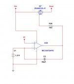
I think the LM2679 tries to maintain 1.21V between the feedback and the ground, just like the LM317 tries to maintain 1.25V between out and ref pin. This is a simple model I have built for it.
Why do I need a very fast op-amp? Considering the PSU uses an op-amp to sense the current, one op-amp to drive the current limiting FET and another op-amp to drive the voltage output FET? Edit: I was thinking maybe a delay would be needed to avoid oscillations?
Why do I need a very fast op-amp? Considering the PSU uses an op-amp to sense the current, one op-amp to drive the current limiting FET and another op-amp to drive the voltage output FET? Edit: I was thinking maybe a delay would be needed to avoid oscillations?
Attachments
- Status
- This old topic is closed. If you want to reopen this topic, contact a moderator using the "Report Post" button.