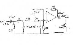
Ok fellows, here´s a drawing of the output stage in my CD-player. Since i´m planning to rebuild the thing using tubes instead of opamps I´d like to know the Fo of the filter.
Is there anyone who can help me with this, I have no simulation software at all and my active filter skills are virtually non-existent.
Thanks in advance!
Is there anyone who can help me with this, I have no simulation software at all and my active filter skills are virtually non-existent.
Thanks in advance!
Attachments
An externally hosted image should be here but it was not working when we last tested it.
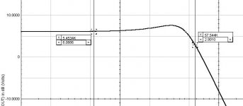
-0.50dB at 9.8KHz
-1.00dB at 14KHz
-1.92dB at 20KHz
-3.01dB at 26.2KHz
-6.02dB at 41KHz
-6.64dB at 44KHz
-17.1dB at 100KHz
> I'd like to know the Fo of the filter.
Not that simple. It's not a Butterworth. It may be a Bessel. But I think it is just convenient part values. I really hope there is some bump somewhere else: -2dB at 20KHz seems a bit lame.
You could just keep the same filter parts, replace the opamp with a tube. Take filter feedback from the tube cathode (no cathode bypass cap, it has to work as a cathode follower). If you can accept unity gain instead of Gv=2, take your audio output from the cathode. If you want gain or the plate sound, build a "split load phase splitter" except the cathode resistor say 10K, plate resistor 22K. Cathode feeds the filter, plate feeds the output with gain of 2.
I would not hand out thanks just yet......
"my active filter skills are virtually non-existent."
There seems to be a lot of that going around. I am pretty sure that your schematic is drawn incorrectly since the 1.5nF cap goes to the output of the op amp for a Sallen Key filter, NOT TO THE INVERTING INPUT. Correcting that gives a third order filter that has about 1.5
dB of peaking around 28 KHz and is down 3 dB at around 57 KHz. Be careful about free advice, you often (more often than not on forums) get what paid for it.
Fred
Attachments
Damn, you´re right!! Of course the cap should be connected to the output!! That explains a few things...
I´m sorry for any trouble.
But, the fact that the output stage acts as an amplifier instead of a buffer must have som impact on the filter performance, right?
How do I predict this??
I´m sorry for any trouble.
But, the fact that the output stage acts as an amplifier instead of a buffer must have som impact on the filter performance, right?
How do I predict this??
> the 1.5nF cap goes to the output of the op amp for a Sallen Key filter, NOT TO THE INVERTING INPUT.
It can be done either way.
For all the Classical (Butter, Bessie, Tschebi...) filters, you need "gain". There are two ways to do this. One is to use an amplifier with "small" gain: typically about 1.3 for low-Q filters. Another is to use a unity-gain amplifier and stagger the component values. For hi-Q this quickly leads to impossible values, but for low-Q it is quite practical and cheap. And if you do not need anything as "optimized" as the Classic Responses, a random collection of parts can make a useful filter even if they violate all the "rules".
This one is tricky. This is a 3-pole filter with all three poles at similar impedance levels. It interacts like crazy. There isn't a clean way to solve this with pencil and paper.
Fuling- ignore my plot above. I made a MAJOR goof. I neglected the impedance of the feedback resistors. Assuming your schematic is correct as you drew it (which is dubious), this is the response:
If there is another 1-pole filter at about 30KC somewhere in there (DAC load cap?), this actually gets nice.
Assuming Fred is correct and filter injection comes from a gain=2 amplifier output, I get (of course) essentially Fred's plot:
All this ignores op-amp (or tube) error, since you did not specify the opamp used. The error will be small but not negligible. A 741-class chip will be more than a few dB off from the ideal plot at 20KHz, and above that forget accuracy. The common TL0 and JRC chips are better but still won't match the ideal simulation above the audio band.
Why doncha just measure it so Fred and I don't have cause to squabble?
It can be done either way.
For all the Classical (Butter, Bessie, Tschebi...) filters, you need "gain". There are two ways to do this. One is to use an amplifier with "small" gain: typically about 1.3 for low-Q filters. Another is to use a unity-gain amplifier and stagger the component values. For hi-Q this quickly leads to impossible values, but for low-Q it is quite practical and cheap. And if you do not need anything as "optimized" as the Classic Responses, a random collection of parts can make a useful filter even if they violate all the "rules".
This one is tricky. This is a 3-pole filter with all three poles at similar impedance levels. It interacts like crazy. There isn't a clean way to solve this with pencil and paper.
Fuling- ignore my plot above. I made a MAJOR goof. I neglected the impedance of the feedback resistors. Assuming your schematic is correct as you drew it (which is dubious), this is the response:
An externally hosted image should be here but it was not working when we last tested it.
If there is another 1-pole filter at about 30KC somewhere in there (DAC load cap?), this actually gets nice.
Assuming Fred is correct and filter injection comes from a gain=2 amplifier output, I get (of course) essentially Fred's plot:
An externally hosted image should be here but it was not working when we last tested it.
All this ignores op-amp (or tube) error, since you did not specify the opamp used. The error will be small but not negligible. A 741-class chip will be more than a few dB off from the ideal plot at 20KHz, and above that forget accuracy. The common TL0 and JRC chips are better but still won't match the ideal simulation above the audio band.
Why doncha just measure it so Fred and I don't have cause to squabble?
- Status
- This old topic is closed. If you want to reopen this topic, contact a moderator using the "Report Post" button.
- Home
- Amplifiers
- Solid State
- Need help with simulation