I'm planning my active build, and have these ICs already.
I'm aware that for 4 ohm loads the parallel option is recommended, however my speakers are 8 ohm, and their lowest impedance is 6 ohm.
My plan is to either:
(1) Use one IC for L and R channel, bass on one 'half' and treble on the other.
(2) Use an IC per driver, in parallel mono.
Will i really notice a difference using 4 ICs rather than just 2 in stereo configuration?
Last edited:
It's not so much that you will notice a difference whether paralleled or not, though it will make life easier for the chips and there will be lower distortion (and you can go higher on the rail voltages), but more that you don't really want to be mixing signals (bass and treble) on the one chip. Both the thermal waves from large power draws at LF and any sagging (and signal) on the rails will be directly there on the treble section.
One of the advantages of active is that the LF part can clip or somehow run out of steam without taking the treble section with it as well. Ideally, or at some time in the future, you would have different supplies for treble and bass amps.
Depending on how loud you want it to go (and it won't be that loud into 8 ohm speakers) your two choices are two chips, one doing both basses and the other doing both trebles, or four chips in the same config but paralleled. Personally I would go for paralleled for two or three reasons. There is less chance to make a mess around the various V+ and V- with the decoupling caps there, you're more likely to avoid crosstalk in your layout, and you can get your rail voltages up to around +-40V, or a smidgeon more, while not putting the chips under any great pressure. A slightly better amp will probably come from +-37V and some of this loss of peak output will be made up by the fact that one amp can effectively add to the output of the other when spanning the crossover region which can't happen with a single amp. Having said that, I personally would probably be brave and get the very maximum I could out of the chips (Ie 42V, IIRC), knowing that they would be driving an equivalent 16 ohm load and that the arrangement is perfectly capable of driving a 1.5 ohm actual load!
Okay, use one chip for bass. . . and then use a separate chip and separate power circuit for mids&treble. All of the effort strain and noise of big bass currents will not affect your mids&treble that way.
If you have only one transformer, then simply use a DC power board, and put diodes (or regulators or capmulti) in series to the DC power cable that goes to the mids&treble amplifier. Giving the mids&treble amp functional power decoupling may help block some of the noise from the bass amp so it doesn't get into the mids&treble amp.
P.S.
Since two different supplies would be better, in that case I would favor LM4780 bass amp teamed with LM1875 mids&treble amp.
for a minute there I thought Id asked a daft question!
Thank you both for your responses!
This was one of those threads I almost wish I hadn't posted, but now I am glad I did!
PSU fluctuations and isolating that side of things hadn't occurred to me, and I agree Daniel, LM1875 for tops would be nice....but I don't have any!
I have 4780, 3875, 3876, 3886...
Both of your posts make a great deal of sense to me, and I was only just starting to consider HOW I was going to approach the PSU/s, I considered that shared PSUs wouldn't be ideal. I had no idea it was such a bad idea. Thank goodness I didn't try it.
Perhaps then I should use one 4780 parallel per channel for bass, and then either:
A single 4780 for highs, with separate PSU(Crosstalk shouldn't be too bad?
its a stereo IC isnt it?)
Or just a pair of 3875/6/3886 instead.
hmmmmm
Thanks again guys")
Thank you both for your responses!
This was one of those threads I almost wish I hadn't posted, but now I am glad I did!
PSU fluctuations and isolating that side of things hadn't occurred to me, and I agree Daniel, LM1875 for tops would be nice....but I don't have any!
I have 4780, 3875, 3876, 3886...
Both of your posts make a great deal of sense to me, and I was only just starting to consider HOW I was going to approach the PSU/s, I considered that shared PSUs wouldn't be ideal. I had no idea it was such a bad idea. Thank goodness I didn't try it.
Perhaps then I should use one 4780 parallel per channel for bass, and then either:
A single 4780 for highs, with separate PSU(Crosstalk shouldn't be too bad?
its a stereo IC isnt it?)
Or just a pair of 3875/6/3886 instead.
hmmmmm
Thanks again guys
Hi,
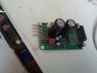
I am planning on using paralleled LM4780 amps in my new build. The boards are designed to be used only in parallel and I will use five for a three way; a pair bridged for woofer and mid. They are 75 x 50 mm so that they will fit across a 300 mm wide heatsink.
I am planning on using paralleled LM4780 amps in my new build. The boards are designed to be used only in parallel and I will use five for a three way; a pair bridged for woofer and mid. They are 75 x 50 mm so that they will fit across a 300 mm wide heatsink.
Attachments
Yes, they are stereo chips. To the point that the V+ and V- go separately to each of what is effectively a 3886 chip on board, so it's worth checking the paperwork to make sure you have this right.
I have to say that since you have got the thermal tracking already there by virtue of being on the same chip, I would also be very tempted to bridge them since they are driving an 8 ohm load. Then you can get some real headroom. Just one more thing to add to the thoughts.
I have to say that since you have got the thermal tracking already there by virtue of being on the same chip, I would also be very tempted to bridge them since they are driving an 8 ohm load. Then you can get some real headroom. Just one more thing to add to the thoughts.
Hi,
IMO two chips parallel on the bassmids and single chip for
treble. 3 chips but thermally it makes the most sense to me.
Adding a 4th chip for the treble doesn't make sense to me.
Common supply but isolate the treble chip with series diodes in
the power supply lines to the local (to the chip) supply capacitors.
Some may argue but modest cap values on the PS board and
much bigger than usual caps near the chips is IMO a decent plan.
rgds, sreten.
Last edited:
I can vouch for that!Then you can get some real headroom.
Thanks Sreten, i also considered it a little wasteful to use a chip each for treble. Of course 3 heatsinks instead of 2, in order to equalise their heat dissipation, is a little awkward.
Bridging may indeed be on the cards now, although my aim in using parallel was to ensure i had ample current capacity at the limits of the amps power, for e.g. using 40V rails. Bridging means ill have to rejig gain to match the treble amp.
Bridging may indeed be on the cards now, although my aim in using parallel was to ensure i had ample current capacity at the limits of the amps power, for e.g. using 40V rails. Bridging means ill have to rejig gain to match the treble amp.
Thanks Sreten, i also considered it a little wasteful to use a chip each for treble. Of course 3 heatsinks instead of 2, in order to equalise their heat dissipation, is a little awkward.
Bridging may indeed be on the cards now, although my aim in using parallel was to ensure i had ample current capacity at the limits of the amps power, for e.g. using 40V rails. Bridging means ill have to rejig gain to match the treble amp.
Possibly a touch wasteful but I think it will likely pay dividends in that you have the same output impedance on both amps and so secondary characteristics will be the same, say when mixed with the same cables etc. I don't see you need to change your choice of gain at all, tho' some sort of trimmer, probably on both will be a must in any event in an active x-o.
You'll still have ample current into 6/8 ohm speakers. As I have written elsewhere in the last couple of days, the current through the speaker is what determines the listening level, so not as much changes as people think. Use 30 or 35V and you also have a lot less dissipation through each of the devices than you would at, say, 40V.
@Sreten et al. I don't understand how it seems to have become a "fact" that diodes will isolate the power supplies, one from the other. It's a diode, so if the rails sag so will the voltage on the other side, just 0.6V lower. And you're introducing additional rectification on the rails (which was never a nice thing in the first place), only now it is completely dependent on how much charge your local caps can hold - particularly as to the point in time when they start charging again (which could be almost unrelated to the music). I see what people are getting at, but it strikes me as misguided.
No, you're correct! We're slightly at cross purposes. Bridging does add 6dB because you now have twice the swing. I was getting at the fact that in practice you will turn the volume down, so won't have twice the current and 4x the power (unless you want it!).
Drop the gain of each half down to 12 or 15 and you'll be fine.
I don't agree in principle (especially to save £6) with having different amps on treble and bass. I know its excessive, but it's not as though you're splashing out on a pair of 135s to drive two tweeters. Even using 3886s you'll have different gain and different closed loop bandwidth and a different output Z. And you're making the layout task twice as hard by not repeating it.
Anyway, I think it will be a much more exciting amp to have than just another gainclone.
PS (I see that isn't 100% clear. You can do whatever you like with the gain, as long as they match. If you want close to a standard 26dB or 30dB power amp gain, then you will have to drop the individual gains. I prefer bandwidth over gain, anyway, though that's not a common opinion on some of the forums.)
Last edited:
Haha ok. I get so used to thinking I'm correct (in error) that i have to check myself
I was thinking of the same gain for each section, assuming output Z and bandwidth would be equal, despite it perhaps not being the greatest idea to attenuate input signal, only to gain 26db or so. But its the simplest way, and simplicity has its benefits.
This is mainly because i was planning to buy PCBs rather than etch my own. Lazy of me really, but the 4780 looks like a royal pain to route without using double sided board. I etch regularly, but the setup is best suited for single sided PCBs, i.e. I can only expose one side at a time, which makes alignment awkward.
But it would be nice to get my own PCB done. Particularly if i manage to integrate the active filters on the board too.
There i go again, complicating my task...
@Sreten et al. I don't understand how it seems to have become a "fact"
that diodes will isolate the power supplies, one from the other. It's a diode,
so if the rails sag so will the voltage on the other side, just 0.6V lower. And
you're introducing additional rectification on the rails (which was never a nice
thing in the first place), only now it is completely dependent on how much
charge your local caps can hold - particularly as to the point in time when
they start charging again (which could be almost unrelated to the music).
I see what people are getting at, but it strikes me as misguided.
Hi,
Choose your poison. The diodes change the interaction of the
two supplies, some think it is better, some think its pointless.
It is pointless with a standard supply and standard value on
board decoupling capacitors. So its also related to supply
design philosophy and topology, really a lot of guessing.
rgds, sreten.
Mondo, I agree that you should buy PCBs, to begin with at any rate. It can sometimes help just to have something physical in front of you, even if it's not how you would do it yourself. And, if you're lucky, you can benefit from someone else having already put their mind to it. Often you can do mods with what you are given.
FWIW, the main concern is to make sure you don't have the thing oscillating. One layout rule that has paid dividends for me is to have the two decoupling caps meet by the chip and then take that meeting point to your Gnd.
I thought the ones we saw on this thread (?) looked OK, especially if they are being done with a eye to bridging. There must be several available here and the chances are that you can look at the layout before you buy.
Active filters on the board? I wouldn't have them too close to the main amp. You want a bit of regulation in between, a properly organised ground and an electrically peaceful environment. It would be nice to just have them slot in on cards, perhaps in place of the coupling caps, but I can't help feel that's getting a bit too close to the high current stuff.
That was my thinking. I built the P3 from the ESP site, using 3055/2955 and it worked ok. I'm not a layout expert, but i don't do too badly really. In the case if the P3, the layout was almost exactly as the schematic diagram, which wasn't optimum really. A touch noisier than i liked, and short cables from the board to ops. Not really how i wanted to do it, but it was a college project with deadlines looming. Each channel was on a 6x4 pcb, so loops were large, relatively speaking.
Whatever i do I'm sure to add more psu reservoir caps, or just make my own psu. Zobel, or recommended output filter will be added for sure.
Whatever i do I'm sure to add more psu reservoir caps, or just make my own psu. Zobel, or recommended output filter will be added for sure.
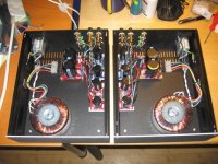
I chose one LM4780 for treble and mids using half the chip (i.e. stereo configuration) for each part and then one LM4780 for the bass (i.e. parallel config) for three channels total. Works great.
Attachments
Last edited:
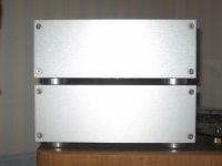
The sides of the chassis are what the DIYAudio store calls "quasi heatsinks" and more than enough for my needs. The day I decide that the system I'm building is worth spending more money and time on I will build something or buy something better. It's always good to have pair of multichannel amps for development and testing.
- Status
- This old topic is closed. If you want to reopen this topic, contact a moderator using the "Report Post" button.
- Home
- Amplifiers
- Chip Amps
- 4 x LM4780 mono, OR 2 x LM4780 stereo: Will I notice the difference?