hello! i am a newbie to the forum. on top of that english is not my mother lanquage. so, my apologies beforehand. and i hope this post is in the right section of the forum
i am in a band (the drummer), and i will soon buy some in ear monitors. (cosmic ears ba4f 4 iems
they have 4 speakers in them, their specifications are these
BA4 | Cosmic Ears
Technical Specifications
i will need a headphone amp to use them, and from what i have read, the best one for that speciic price range is the o2. and from what i read, all the parts could cost around 50 euros. which approximately is the price range of me.
my first question is this.
all the threads i have read about the o2 in the forum, are dated about a year back (which means no group buy which is a pity, i would surely be interested). since that time did you guys find out about a headphone amp in that price range that could deliver better results? what i need of course is for the amp to amplify the sound without distortion hiss etc. i want to be able to listen to the monitor mix the way it is supposed to be heard.
if the o2 is the right amp for me, can you reccomend me the cheapest place to buy the o2 kit that cntains all the parts and box? i am located in europe so, it would be of great help if no usa links were provided. the customs would kill me. id have to pay to much... if there are different places, one that sells the box, one hat sells all resistors etc a,d one that sells the circuit plate, i have no problem.
if there isnt such a place, which is the site that sells the o2 the cheapest? thank you
one last question. i will need to create also a limiter (actually not me, my bassist will do all the soldering etc he is the genious). can you guys please advise me on a good limiter for my headphone amp. should it be just a diode (from what my bassist tells me) or something else? i want to limit sounds that would come from perhaps someone unpluggind the bass cable , or a microphone dropping etc. and hopefully when that does, i wouldnt want the sound in my iems to get all distorted.
anyway, sorry for my long post. thank you all so much, this is an amazing forum
i am in a band (the drummer), and i will soon buy some in ear monitors. (cosmic ears ba4f 4 iems
they have 4 speakers in them, their specifications are these
BA4 | Cosmic Ears
Technical Specifications
- Sensitivity: 122 dB SPL/mW at 1kHz
- Frequency Response: 18Hz-15kHz
- Impedance: 30 Ohms at 1kHz
- Noise Isolation: -26dB
i will need a headphone amp to use them, and from what i have read, the best one for that speciic price range is the o2. and from what i read, all the parts could cost around 50 euros. which approximately is the price range of me.
my first question is this.
all the threads i have read about the o2 in the forum, are dated about a year back (which means no group buy which is a pity, i would surely be interested). since that time did you guys find out about a headphone amp in that price range that could deliver better results? what i need of course is for the amp to amplify the sound without distortion hiss etc. i want to be able to listen to the monitor mix the way it is supposed to be heard.
if the o2 is the right amp for me, can you reccomend me the cheapest place to buy the o2 kit that cntains all the parts and box? i am located in europe so, it would be of great help if no usa links were provided. the customs would kill me. id have to pay to much... if there are different places, one that sells the box, one hat sells all resistors etc a,d one that sells the circuit plate, i have no problem.
if there isnt such a place, which is the site that sells the o2 the cheapest? thank you
one last question. i will need to create also a limiter (actually not me, my bassist will do all the soldering etc he is the genious). can you guys please advise me on a good limiter for my headphone amp. should it be just a diode (from what my bassist tells me) or something else? i want to limit sounds that would come from perhaps someone unpluggind the bass cable , or a microphone dropping etc. and hopefully when that does, i wouldnt want the sound in my iems to get all distorted.
anyway, sorry for my long post. thank you all so much, this is an amazing forum
Are you planning to build it yourself or buy ready made?
When i built my own i bought the PCB and case from Head 'n' HiFi - Walter (nicest quality PCB IMO) as they are in europe, components i ordered from Mouser as i opted for the better quality parts like the Panasonic/WIMA Capacitors, Mil spec resistors etc, basically everything on the right hand column of the BOM sheet. I think you can also buy a complete DIY kit from them too which is probably the most cost effective route if you are in europe.
You could possibly buy the components from RS or another supplier in europe but i find the stocks a little limited and you would end up buying parts from all over the place or having to find suitable replacements, at least with Mouser you can get everything in one order.
as high sensitivity iem your headphones really don't need voltage amplification - usually a step-down function is required - they do however want a low impedance drive
what source, signal levels? - pro line level from mixer while playing? desktop consumer DVD/CD player or portable mp3 player - all have different V -by enough that you really need different selectable attenuation for each to match the iem
often the "best" solution for high sensitivity iem would be quality step-down audio transformers - unfortunantly no commercial off the shelf audio output xfmr are really designed for this special application
but some people actually did act on my suggestion in this head-fi thread http://www.head-fi.org/t/553094/con...icrotransformer-based-impedance-step-down-box
the O2 has gain - any gain is too much
less elegant than transformers, you can step down the V with a resistor divider - you have to size the divider R to waste >90% of the power into it to obtain adequate damping ratio http://www.head-fi.org/t/198828/the-hissbuster-for-sensitive-headphones
Last edited:
hello my friends. i will answer both your questions and add my questions as well.
first of all, i cant build it i am incopetend, but my bassist can do that easily. he has done his fair share of diy things. he has created his own pedals, so it should be fine.
i have already checked head n fi walter. it seems to be a good price. (if there is a european shop with better prices please do tell). so if the soldering etc is pretty straight forward id rather buy the whole diy kit than a ready made o2 amp. i do not have enough money, and i am from greece so i bet you understand the situation here...
i checked the mouser site, but i got lost. i couldnt find an o2 diy kit, or an o2 amp. if i have been blind please share the links with me. i need to spend my money wisely.. otherwise if mouser doesnt sell any more diy kits, id stick with walter. his site hasnt been updated recently, but i hope it is still functional.
jcx, thank you for your valuable input. to be honest i understood less than half of what you shared with me.
so, are you certain that i will not need a headphone amplifier
meaning that i will not need a signal amplification for sure?
the first priority for me will be toi use the headphones for live gigging. the sound engineer will send to me my personal monitor mix to the iems. of course the headphones will need to be hooked somewhere. so even if they do not need amplification as you say (i have no trouble believing that, i just need to be sure so that i know what i need to purchase. and since you seem to know what you are talking about, i follow your lead my friend), they will still need to be hooked somewhere. so in between my iem headphones, and the cable that transfers the signal to me, there must be something. i thought it should be a headphone amp, but if amplification is not needed, what should i get instead?
i did not understand what a low impedance drive is for. couldnt the headphone amp also do that?
if not, then even if i got a headphone amp, it wouldnt be enough by itself, right?
since i will need my iems for gigging which i take very serious, what would be thebest way to assure that the sound i send to my iems is of top quality?
step down audio transformer or a resistor divider? and what would be the difference in expences if i could make both of them? actually and what do these things actually do? the amplifier i know that makes the signal louder. but the divider, what is its purpose? i guess that it doesnt make the volume softer. so what is it needed for? if it just divides the volts, wouldnt that mean that the volume will get lower, or not? i missing something here...
and last but not least, i could also use the iems with my electronic drums or for listening to music from my mobile phone. would i need a headphone amp for these applications or even in these situations, amplification is not needed?
ps1. even if i do not need amplification wouldnt i need to be able to choose the volume level of my headphones? what should be created for that purpose
ps2. i certainly will need a limiter to avoid any feedback getting to my ears. any ideas or schematics of what i should build? thank you
a pro xlr output could go up to +26 dBu (pro line level units are weird to EE types - but basically is saying the output could produce 400 mW into 600 Ohms)
the iem only need 1 mW to give deafening 122 dB SPL in your ear
so you are starting with over 100x too much power/Voltage (yes not the same but lets not overload the op more than I am already) from a pro mixing board output for the iem
deliberately wasting power in a R divider is the cheapest solution
30 Ohm iem probably are "well driven" from ~< 3 Ohm source
so a divider with 3 Ohms in parallel with the iem and say 300 Ohms in series probably puts you in the right ballpark for adapting these sensitive iem to pro audio outputs
other questions are whether the monitor mix aux setting should be the only volume adjustment needed - or if you should have one or two local stepped attenuation switches (and probably mute that you can get to quicker and than yanking the iems from your ears)
the actual V needed by the iem is low enough that shunt diode clippers tapped into the 300 Ohm series R is an option
the pics seem to show a TRS connector for the iem - which means the R,L ground returns are shorted together - but good pro output is balanced - you may need to have the stock TRS connector replaced if you want to plug into balanced outputs
this can all be done without amplifiers, power source - any small project box, Altoids tin or even inline in a XLR inline cable connector shell depending on switching options (local attenuation, mute)
quick sketch - values need to be worked for your exact monitoring drive situation
Attachments
Last edited:
Do you use something like this?
An externally hosted image should be here but it was not working when we last tested it.
hello again and thank you all for your input. words cant express my gratitude for your willness to help me. god bless you
ill answer Avro Arrow's question first, as the answer is easier.
no my friend i do not want to use a wireless iem system. first of all it is too expensive. and second of all since we 9 out of 10 times, have our own sound engineer, it is easy for him to send me my monitor mix through a cable. and then i somehow hook up my iems. (how i do that, is the reason i started this topic though).
bottomline line is i am trying to immitate the function of a wired iem system, without having to amplify anything, since jcx clearly states that it isnt needed!!!
now to jcx's amazing post
i would be lying if i said that i understood everything you said.
i understood really well that we need to have the voltage dropped. and that i dont need a headphone amp!!hooray!!!
i liked what you did with the schematic my dear friend, (though it isnt all clear to me). i really liked the idea of a mute. what i would also think that would be awesome, would be a volume switch, so that i can adjust the volume by myself. this is a must have. i suppose that it is achievable right?
about the balanced and unbalanced signal, i got half of it. i wouldnt want to screw up the jack of my iems, but i guess a little diy box that can transform between balanced and unbalanced signal would be the right way to go,am i correct?
so, to put it in simple words, in order to use the iems for the job i need (aka gigging), i would need 2 boxes. one that dropes down the voltage and watt to one mwatt approximatelly and also has a volume switch, and one box that can do the balanced to unbalanced and vice versa transformation. is that correct? (i forgot to say that if i correctly recognised that you put 2 diodes in the schematic to be used as a limiter, this is wayy cool!! thank you)
my last question about this, is if the quality of the signal, my iems will receive, is quality enough. i hope that no hiss or distorted sound is created through the 2 boxes my bassist will create. thats the reason i will buy the iems in the first place!!!
if i understood everything well enough, if there is a link or schematic i could use for the balanced unbalanced box, it would be really appreciated!!!
as i said before, my bassist will create the box-boxes for this diy project.
i gave him the url of this thread, he read it carefully and has some questions. i will copy paste them here, i hope you can help him.
since the audio signal i will be receiving from the mixer will be balanced, do i have to put a balanced to unbalanced conversion before the schematic you sent? As far as i have understood the bottom rail in the schematic is the ground rail. Also R6 could be swaped for a pot - volume control?
Finaly, the signal i will be receiving is usually in mono. What is required to duplicate it to both iem.
Balanced Line Driver & Receiver (balanced receiver)
thank you all for your help!!! you are making a drummer a very happy man!!!!!
I know $300 is probably a lot more than you wanted to spend, but
something like this is exactly what you are looking for.
Shure P4HW
something like this is exactly what you are looking for.
Shure P4HW
thank you my friend, i agree, but i will never be able to get that, so my only option is diy...I know $300 is probably a lot more than you wanted to spend, but
something like this is exactly what you are looking for.
Shure P4HW
A volume pot complicates things – they just aren't made at such low Z
putting the volume pot in front of a audio step-down transformer looks do-able
it turns out Hammond makes small low Z audio output xfmr
Hammond 148X is 4k:3.2 Ohm, 300 mW output – since you need <<1 mW this xfmr will go way below its 200 Hz spec at the reduced operating V level
these apparently ship from the factory whoever you buy from - 5 in factory stock
http://www.digikey.com/product-detail/en/148X/148X-ND but Newark promises 3 days from factory
next would be locating a low Z log taper volume pot – preferably plastic element but with the power rating to plug into a pro line level output
to keep the low frequencies when driving the xfmr primary you really want low Z, << 4kOhm xfmr pri impedance rating – a 1K pot would be nice
http://www.digikey.com/product-detail/en/91A1A-B28-D10L/91A1A-B28-D10L-ND might work
another option would be to parallel both sections of commonly available duals, paralleled dual 5K probably is easier to find
other things to toss in, play with with actual xfmr in hand:
DC blocking C, maybe a Zobel load to flatten high frequency response to get to the spec'd 15 kHz without peaking
and the mute switch, maybe a level pad
Last edited:
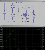
need more info (measure real part) on 148X xfmr to be accurate
low frequency extension and distortion should improve as drive levels decline
really an't say much of anything about leakage L, winding parasitic C that sets the high frequency limit without having the xfmr on the test bench
this may be a start for topology/values:
low frequency extension and distortion should improve as drive levels decline
really an't say much of anything about leakage L, winding parasitic C that sets the high frequency limit without having the xfmr on the test bench
this may be a start for topology/values:
Attachments
Last edited:
my dear friend, you are simply awesome. thank you so much for all you guidance and time you spend replying in this thread.
first of all, let me apologize for not replying earlier. it took me and my bassist some time to understand what you meant in the last 2 posts you made!!!
i think that with your last diagramm, we understood pretty well what is going on.
thank you for advising us on where to put the volume control as well, i wouldnt be able to use this thing without a volume control, at all.
we (my bassist) will try and create this circuit asap and try to experiment with values!
there are a few questions that need to be answered. they may be "noobie" questions for you perhaps, but please bear with us
first of all, the signal (aka the monitor mix) that our sound engineer sends us from his foh console, is balanced, right?
my bassists question is this:
should we let the signal remain balanced, or do we have to make it unbalanced before we hook it up to the thing we are trying to create?if it has to be converted to unbalanced, is there some other thread you can propose that we read, to get grasp what we need to construct?
second question is this: my bassist says that the signal from the foh console is mono (i am not sure about that, but i am a drummer so dont pay any attention to me lol). how can we make sure that both rear buds of my iem headphones, "play" the same thing? we need of course to avoid having one ear bud muted or not playing with the same volume. bassist semms puzzled about that. any help? (i really dont get what he meant i just ask what he told me to ask
last but not least, is the position we should put the diodes to create the limiter
again i am really sorry for the many questions i did. we will surely mention you in our thanx section, in our cd when it comes out, and it will certainly find its way in your inbox, should you be interested in some heavy rock music!!! take care!!! our next gig will be dedicated to you!! hehehe
cheers
balanced drive isn't a problem – I had to put a gnd symbol on the Vsource to keep the software happy but you would just hook the pot terminals to the XLR balanced pair
the 148X transformer's secondary output Z should be so low that both iem can be driven together, paralleled
if you did want to go Stereo then just build a complete duplicate – could even keep the headphone cable TRS connectors since the transformers secondaries float
for the DC blocking C I would choose a bipolar Al electrolytic – say Panasonic SU series
my friend thank you so much!! everything is fully understood!! (by my bassist i mean , lol)
we will order the parts and start experimenting on values etc. as soon as we have it ready we will post here. god bless you.
ps. if we find any problems in the construction, we will seek advice in this thread. thank you once again
we will order the parts and start experimenting on values etc. as soon as we have it ready we will post here. god bless you.
ps. if we find any problems in the construction, we will seek advice in this thread. thank you once again
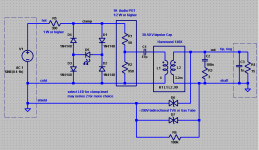
I might add a couple of TVS or Gas Tube Surge Arrestors and a charge draining R across the transformer pri-sec since the transformer pri-sec insulation is only rated to 250 V and the iem could serve as ESD antenna - probably best terminate to the shield of the XLR
my 1st thought would be to go with near 200 V surge arrestors to give the most use of the xfmr isolation rating while still protecting it from insulation breakdown
the volume pot makes it harder to find a good place for diode clipping since a goal is to keep the drive Z to the xfmr pri as low as possible and a simple passive clipper needs added series R
higher drive R increases low frequency distortion from the cheap core material
but since the application is only Rock and Roll maybe the clipper is more important - you tell me - what max SPL level would be expected in a clipper?
hello my friend again. it took us some time to understand once again, what you mean!! we (actually my bassist) are nowhere near your expert level, to fully grasp what you say!! sorry about that.
actually my bassist says " this guy is tottally crazy!!!". in a good way!!! he rates you as his god!!!
back to the topic. what the bassist doesnt fully understand, is where thesurge arrestors should be placed exactly, in the schematics you provided to us, a few posts back. how they should be connected exactly... perhaps this is a noobie question, but i had to ask. sorry if the answer is so simple...
about spl level, i didnt get what you mean. if you mean how loud the sound from my iems will be, id say somewhere between 85 and 120 db? anything above that, we wouldnt want. and a clippping would be surely above that. but then again, i am almost sure, that this is notwhat you asked... so, apologies for my ingorance. anyway thank you for all your help
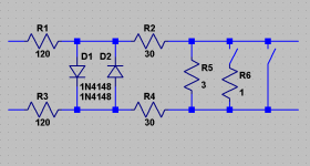
more complete drawing
the parts in the dashed boxes are just for the simulator
the clamping level is set by D5 - can be a LED or 2 in series
my sim shows for ~ 120 dB SPL the clamp LED should have ~ 4Vfwd, ~50 mA peak - lots of options, easy to select from Digikey tables
but the peak current is higher than many "indicator" LED ratings so can't just use junk drawer parts - must look at datasheet
LED Vfwd varies with color, type of semiconductor material - for 4 V probably would be bule or "white" - which is a blue LED with some phosphors in front
make sure the surge arrestors are bidirectional - equal clamping V both directions
Attachments
Last edited:
hello my dear friend. we thank you so much for your contribution to our project. finally we are in the process of ordering the components from mouser!!!
our bassist has the basket almost ready for order. but before he finalizes our purchase, he has 2 very important questions to ask you, so that we can order the right parts. here they are
question 1:
The input and output jacks should be plastic so that the sleeve does not touch the metal enclosure? Shall this apply to both input and output or only one of them? (our sound engineer told us that he will send us balanced TRS)
question 2:
We have trouble narrowing down our choices concerning the TVS. The 200V you specified are the breakdown voltage? What about the other two specifications - operating and clamping?
thank you so much, you are definitely the ultimate diy guru!! we would be lost without your guidance! god bless you
carrying the chassis/shield gnd through from input to the headphone common output is an option - then the surge arrester and charge drain R aren't needed
I suppose 1/4'' TRS balanced patch cords are commonly used - but I dislike the idea, would rather see XLR
at least the iem headphone out can be 1/8" TRS jack/socket so there's no way to plug backwards
except for the 1/4" - 1/8” TRS adapter that comes with the iem - lose it if you go for a 1/4" TRS balanced line in jack on your box
the Mouser page for the Bourns 91A1A-B28-D10L has the power rating wrong - the single section conductive plastic Audio taper is 1/2 W
Last edited:
- Status
- This old topic is closed. If you want to reopen this topic, contact a moderator using the "Report Post" button.
- Home
- Amplifiers
- Headphone Systems
- some question about headphone amp (possibly the o2)