Hi all, I've been hearing about the CS3318 a fair bit recently, and how it's supposed to exhibit lower noise than the PGA2310 in use. Well, I've found the PGA2310 does have some noise and I'm not sure why that should be, but I may well have an application for a 6-8 channel volume coming up and am learning PCB layout, which the CS3318 certainly requires!
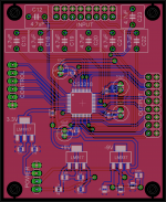
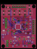
So, here's my attempt, it's my first real design in Eagle other than a practise board so it's probably far from optimal. The IC package is from another device in the database and wired up according to the datasheet. Voltage regulators are adjustable since a -9V fixed couldn't be found, they should produce a little under +/-9V.
A couple of things:
Otherwise, it's pretty much a standard application with on-board regulators. Any input appreciated!
So, here's my attempt, it's my first real design in Eagle other than a practise board so it's probably far from optimal. The IC package is from another device in the database and wired up according to the datasheet. Voltage regulators are adjustable since a -9V fixed couldn't be found, they should produce a little under +/-9V.
A couple of things:
- The coupling capacitors are perhaps a bit small but I wanted film and not to make the board too massive, they can by bypassed with wire links if preferred but maybe a double-hole mounting which could accept electros would be useful?
- Will the ground fill under the IC suck too much heat while soldering? Perhaps it should be more isolated but I'd need to draw a seperate polygon for this I think, and if I did that, perhaps a hatched fill would make sense.
Otherwise, it's pretty much a standard application with on-board regulators. Any input appreciated!
Attachments
Last edited:
Hi some tips:
- Please use 10 µF bypass caps on R8 and R10. Explanation would be an insult")
- Use a better 3.3 V regulator. Won't cost more than the current one.
- Place the 100 nF decoupling caps much closer to the chips pins.
- maybe the input pins should be referenced to GND by means of 100 kOhm resistors (so before the caps) ? It will avoid clicks/plops when plugging cables in and out ...
- don't you need the pull up resistors on pin 5 and 6 (check data sheet) ? Adding the pads won't cost money and maybe you will need them in your application later on.
- I would use standard electrolytic caps or SMD tantalums for C11, C14 and C16. I am not so sure if LM317/LM337 like MLCC ceramic caps with very low ESR at their outputs.
- what about output caps ? The CS3318 has max. 5 mV offset so maybe I am overcautious. I would definitely use 100 Ohm stopper resistors on each output
- mmmm, just googled this and I think some of my comments are justified : http://www.cirrus.com/jp/pubs/rdDatasheet/CDB3318_DB2.pdf
Keep the film caps, you won't regret it. Electrolytic caps won't bring better performance, on the contrary.
- Please use 10 µF bypass caps on R8 and R10. Explanation would be an insult
- Use a better 3.3 V regulator. Won't cost more than the current one.
- Place the 100 nF decoupling caps much closer to the chips pins.
- maybe the input pins should be referenced to GND by means of 100 kOhm resistors (so before the caps) ? It will avoid clicks/plops when plugging cables in and out ...
- don't you need the pull up resistors on pin 5 and 6 (check data sheet) ? Adding the pads won't cost money and maybe you will need them in your application later on.
- I would use standard electrolytic caps or SMD tantalums for C11, C14 and C16. I am not so sure if LM317/LM337 like MLCC ceramic caps with very low ESR at their outputs.
- what about output caps ? The CS3318 has max. 5 mV offset so maybe I am overcautious. I would definitely use 100 Ohm stopper resistors on each output
- mmmm, just googled this and I think some of my comments are justified : http://www.cirrus.com/jp/pubs/rdDatasheet/CDB3318_DB2.pdf
Keep the film caps, you won't regret it. Electrolytic caps won't bring better performance, on the contrary.
Last edited:
Great suggestions, thanks!
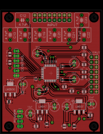
I've implemented most of them. To be specific, I plan that this might get used in a multi-channel audio interface to create a system which can use PC based DSP crossovers. The signal chain would be:
USB-I2S - Multi-channel DAC - CS3318 Volume - Line drivers
With a microcntroller board too naturally. For this reason, the the input resistors and output coupling capacitors can be unused since the line driver would remove DC offset and the DAC will be permanently linked. Power on/off muting would occur on the line driver board, as far upstream as possible. The 100 Ohm output stoppers are a good call regardless of whether you directly drive a coax or not so I included them.
I'm not sure if the new 3.3V regulator represents much of an upgrade but it should do the job of providing the 1mA or so the logic interface needs. The 100uF electro easily satisfies the ESR requirements and at 10V rating is quite compact. I had planned to use SPI interfacing but you're absolutely right, why not include pads for the 2k pull-ups in case, so they're added.
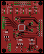
I moved onto the PCB design quite quickly as this was mostly an exercise in learning PCB design in Eagle and so I missed out tricks like the feedback filter for the LM317/337 but they've now been added. I managed to add these without increasing board area at all, though the silk-screen might benefit from some adjustment. +/-9V Regulator output caps are now just 10uF electros.
I would hope the CS3318 100nF bypass are all close enough now, I've certainly done far worse and never had stability issues with op-amps.
Thanks again and any further comments are welcome!
I've implemented most of them. To be specific, I plan that this might get used in a multi-channel audio interface to create a system which can use PC based DSP crossovers. The signal chain would be:
USB-I2S - Multi-channel DAC - CS3318 Volume - Line drivers
With a microcntroller board too naturally. For this reason, the the input resistors and output coupling capacitors can be unused since the line driver would remove DC offset and the DAC will be permanently linked. Power on/off muting would occur on the line driver board, as far upstream as possible. The 100 Ohm output stoppers are a good call regardless of whether you directly drive a coax or not so I included them.
I'm not sure if the new 3.3V regulator represents much of an upgrade but it should do the job of providing the 1mA or so the logic interface needs. The 100uF electro easily satisfies the ESR requirements and at 10V rating is quite compact. I had planned to use SPI interfacing but you're absolutely right, why not include pads for the 2k pull-ups in case, so they're added.
I moved onto the PCB design quite quickly as this was mostly an exercise in learning PCB design in Eagle and so I missed out tricks like the feedback filter for the LM317/337 but they've now been added. I managed to add these without increasing board area at all, though the silk-screen might benefit from some adjustment. +/-9V Regulator output caps are now just 10uF electros.
I would hope the CS3318 100nF bypass are all close enough now, I've certainly done far worse and never had stability issues with op-amps.
Thanks again and any further comments are welcome!
Attachments
Last edited:
Much better but at least one of the 100 nF can be closer.
Getting away with it = not going for optimal performance.... Better do it right at once and chances are likely that you will indeed never have stability issues
If you add GND reference resistors and a control board I would not be surprised if some members will call for a Group Buy ....
I would hope the CS3318 100nF bypass are all close enough now, I've certainly done far worse and never had stability issues with op-amps.
Getting away with it = not going for optimal performance.... Better do it right at once and chances are likely that you will indeed never have stability issues
If you add GND reference resistors and a control board I would not be surprised if some members will call for a Group Buy ....
Last edited:
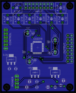
You're right, it's a high performance chip and if I'm going to the trouble/expense to get boards made I may as well get it as refined as possible at the design stage. I will move those screw holes outward too Nisbeth, thanks! Easy to forget how tiny this is really!
I'm up for producing a group buy though I will need a completed CS3318 board in my hand to test the software with, couldn't be confident of that working without it, but that's not to say a control board couldn't be laid out prior to completing the software. A PIC18F series will most likely be employed and support for rotary encoder, remote control and LCD is planned.
I'm unsure what you mean by ground reference resistors? Are these the ones for referencing the CS3318 internal gain stages, in which case the design would need substantial alterations.
Just resistors from each input to GND (before the caps) to avoid plops when plugging in devices. You don't need them but members of a GB probably will. Maybe it a good idea to add pads for healthy input cabling instead of ribbon cable with all its crosstalk problems. The reference design is a very good starting point. Cirrus used PCB mount RCA connectors which are a relief considering wiring. I would keep tedious wiring to an absolute minimum as it is prone to problems, looks terrible and it costs money and a lot of time especially when custom cables have to made. Optimally you could throw the board in a case, just connect relatively simple power supply and control wiring and you're ready to use it. Adding RCA connectors will be a large benefit afterwards ! They are omitted often because of their initial cost but then one tends to forget cabling costs time and money too. Just imagine your self wiring the future PCB in a case and now think again: why do I make it like this ?
Same could count for output caps. Adding the pads + GND reference resistors there too won't cost much and one can DC couple amps with this board. On the other hand: 90 % of amps already have an input caps so you could skip these. It would make the board more versatile but also larger. Drawback is that one needs to use jumpers when the caps are not needed.
You could also think about adding rectifiers and filter caps so that the board will be self powered. And while you are at it you could add the control PCB at the same time This non modular approach will be a hit in 2014 ! It is called "Complete Designing". Please join it as you can be a CDer too Our friend Rudi, an avant-garde CDer, was converted long ago:
http://www.diyaudio.com/forums/group-buys/237302-versatile-comfortable-passive-pre-amp.html
As a mounting hole fundamentalist I can only agree in astonishment (that I hadn't noticed it)
Same could count for output caps. Adding the pads + GND reference resistors there too won't cost much and one can DC couple amps with this board. On the other hand: 90 % of amps already have an input caps so you could skip these. It would make the board more versatile but also larger. Drawback is that one needs to use jumpers when the caps are not needed.
You could also think about adding rectifiers and filter caps so that the board will be self powered. And while you are at it you could add the control PCB at the same time
This non modular approach will be a hit in 2014 ! It is called "Complete Designing". Please join it as you can be a CDer too Our friend Rudi, an avant-garde CDer, was converted long ago:http://www.diyaudio.com/forums/group-buys/237302-versatile-comfortable-passive-pre-amp.html
Looks very good. Might I suggest that you move the screw holes closer to the sides of the board - especially the top ones look like they might be difficult to access if the caps are populated.
/U.
As a mounting hole fundamentalist I can only agree in astonishment (that I hadn't noticed it)
Last edited:
I have been playing with the CS3318 and had some issues with it:
1. Do NOT let it run without the digital powersupply, the analog circuits start to oscillate and burn..........
2. The mute input must be terminated to ground or VD, otherwise crosstalk from the control lines will cause a severe distortion in the analog outputs.
3. Analog powersupply decoupling as mentioned in the datasheet is done wrong, should be caps from rail to ground... and not between rails.
3. Analog powersupply decoupling as mentioned in the datasheet is done wrong, should be caps from rail to ground... and not between rails.
On the contrary: this is correct. Cirrus decouples rails and between V+ and V- which is both old fashioned and good but you don't see it much in reality as it is a forgotten technique it seems. Data sheet also mentions decoupling from Va+ to Va- in text. Please check their reference board where they did it like that on a real PCB. Their engineers would not make the same "mistake" twice I hope:
http://www.cirrus.com/jp/pubs/rdDatasheet/CDB3318_DB2.pdf
People using OPA627 and OPA637 know the caps from + to -. It is the only way to keep those opamps doing what they have to do optimally...
Last edited:
On the contrary: this is correct. Cirrus decouples rails and between V+ and V- which is both old fashioned and good. Data sheet also mentions this in text. Please check their reference board where they did it like that on a real PCB. Their engineers would not make the same "mistake" twice I hope:
http://www.cirrus.com/jp/pubs/rdDatasheet/CDB3318_DB2.pdf
Ok, if some noise enters for example the positive rail, where should it go? To the ground and not to the other rail........
Wrong thinking, it's about closing current loops. Noise should go to the point with lowest impedance to GND. Noise does not have much impact on the other rail as the opamps itself has a certain PSRR.
As said it is an old but good technique to keep some high speed opamps performing optimally. If memory serves me right it also is a way to compensate for a technical imperfection in the opamps output transistors but I tried to google it but could not find it. Anyway I decouple high speed opamps like this since ages and some won't perform good without this form of decoupling (like OPA627/637). One can also add series resistors in supply lines but I don't like to see my output signal modulated on those resistors so I omit these if the deice is "silent". Ferrite beads are very effective too (before the caps) but this is another subject.
As said it is an old but good technique to keep some high speed opamps performing optimally. If memory serves me right it also is a way to compensate for a technical imperfection in the opamps output transistors but I tried to google it but could not find it. Anyway I decouple high speed opamps like this since ages and some won't perform good without this form of decoupling (like OPA627/637). One can also add series resistors in supply lines but I don't like to see my output signal modulated on those resistors so I omit these if the deice is "silent". Ferrite beads are very effective too (before the caps) but this is another subject.
Last edited:
It is not "wrong" to add decoupling from V+ to V- nor is it "wrong" to forget it with relatively slow devices. BTW when decoupling between rails one must also decouple rails to GND.
It just is a good way for keeping high speed opamps performing best. You don't need them with the darn NJM4580s as used in equipment (cheap and slow, only used because of their low price).
Cirrus does know best what kind of opamps they use in the chip and if they "prescribe" how to decouple their opamps the best way I would follow that advice.
Last edited:
It is not "wrong" to add decoupling from V+ to V- nor is it "wrong" to forget it with relatively slow devices. BTW when decoupling between rails one must also decouple rails to GND.
It just is a good way for keeping high speed opamps performing best. You don't need them with the darn NJM4580s as used in equipment (cheap and slow).
Cirrus does know best what it uses in the chip and if they "prescribe" how to decouple their opamps the best way I would follow that advice.
Do not follow datasheets blindly these days, they are full of faults and ommisions.... The CS3318 datasheet also, ommissions in powersupply sequencing and mistakes in pin listings.....
Proper opamp decoupling, see figure 2:
http://www.analog.com/static/imported-files/tutorials/MT-101.pdf
As a long-time user of the 3318, I urge you to also bring out the reference (or ground) pins of each input and output next to the particular i/o pin.
If you lump every ref pin together to a central ground, you get much less performance from this chip then possible.
Keeping each i/o paired to an actual input/output signal as long as possible improves the S/N ratio and the distortion performance.
There is a very good reason why they went to this expensive route to almost double the number of pins!
jan
Thanks for posting that link: it is a good document but please see the second (!) reference to a much older but even more valuable document. The link in the document is broken but I regoogled it.
It is here :
http://www.gmee.deit.univpm.it/biblioteca/sala_tecnica/scaffale_dispositivi/instr_amp/AN-202.pdf
It is not that hard to get used to a technique one does not know (yet). Again: think high speed opamps, think current loops. Since high speed devices are more often used decoupling should get more attention than it got till now. Let's say that one can use a 741 without any decoupling but try this with a high speed opamp...
The third reference in the document you linked is a good read too (same author as the other document):
http://www.analog.com/static/imported-files/application_notes/2904748046167431066AN-342.pdf
Last edited:
Good discussion here, it certainly shows how much more sophisticated a 'universal' design can need to be compared to an application specific one.
To implement these changes we will need to accept a larger board size and eventual higher cost but I will try to be as efficient as I can with it. Here's what I propose:
Thanks all, I will update you when I have made the changes!
To implement these changes we will need to accept a larger board size and eventual higher cost but I will try to be as efficient as I can with it. Here's what I propose:
- Input discrage/terminating resistors, probably around 33k to avoid degrading performance with Johnson noise.
- So is the decoupling used acceptable? The decoupling to ground is back at the voltage regulators so is it too far away? However there is no analogue ground pin as such, only signal grounds, so I'm assuming this is the correct location for it.
- I'm doubtful about output coupling capacitors as I think few will need those and as you say, if the pads are added we all need to use jumpers, plus additional board area.
- In/out connectors I think I'll change to two sets of 8 2-pin Molex style, rather than the IDE/cluster type, which needs ribbons ideally. RCA on-board would easily double board area and personally I wouldn't want that as neither input or output would be directly interfaced from the chassis. Panel-board wiring is always possible with the Molex.
- I could integrate the control board to it, certainly most manufacturers do this, but for DIY people may prefer the modular approach. It'd even be perfectly acceptable to produce your own control boards using veroboard if people prefer to save money and roll their own. Depends if people agree that my control board offers all the functionality they could need? I wasn't particularly planning to include menus for multi-channel level balancing (rather I'd set it in the firmware) but certainly some people might like this?
- A watchdog chip shall be added to monitor the 3.3V rail, and if it fails, put the CS3318 into reset, disabling the analogue systems. Good call ds23man!
- The MUTE control input shall be linked to GND with a resistor, say 10k?
- It's a challenge but I can try to bring out the individual GND references to those input and output Molex headers since you say it can bring about improved performance.
Thanks all, I will update you when I have made the changes!
Last edited:
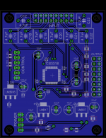
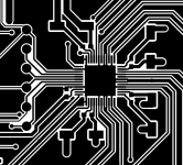
With regard to bringing out the Input/Output GND references to their respective headers, it's curious to note that on their own evaluation board Cirrus have lumped the grounds together underneath the IC package exactly as in my current revision (rotated to match the orientation of my board):

where the measured THD+N plot shows as the IC specification level of -112dB. I'm gussing the main benefit of seperating the ground paths out to the headers is in reducing crosstalk by modulation of grounds by strong signals on adjacent channels? It does call into question why they have gone to the effort to provide all those seperate references if they then go on to bond them directly together on their own reference board, but regardless I suspect an external ground tie point is lower impedance than connecting inside the device package.
where the measured THD+N plot shows as the IC specification level of -112dB. I'm gussing the main benefit of seperating the ground paths out to the headers is in reducing crosstalk by modulation of grounds by strong signals on adjacent channels? It does call into question why they have gone to the effort to provide all those seperate references if they then go on to bond them directly together on their own reference board, but regardless I suspect an external ground tie point is lower impedance than connecting inside the device package.
Attachments
My totally unscientific opinions
RCAs onboard is generally annoying for me, because not only does it cost more in terms of board area, it also ties you to specific connectors and to a specific case mounting.
/U.
Input caps are probably a good idea, but output caps I think should be left out. Normally I would expect that you have more control over which poweramp(s) are being used than over which sources are connected. If the input side is capacitor coupled, all you need to ensure is that the subsequent power amp can handle the offset (or has capacitors in the input) generated by the CS3318 itself.
- I'm doubtful about output coupling capacitors as I think few will need those and as you say, if the pads are added we all need to use jumpers, plus additional board area.
- In/out connectors I think I'll change to two sets of 8 2-pin Molex style, rather than the IDE/cluster type, which needs ribbons ideally. RCA on-board would easily double board area and personally I wouldn't want that as neither input or output would be directly interfaced from the chassis. Panel-board wiring is always possible with the Molex.
RCAs onboard is generally annoying for me, because not only does it cost more in terms of board area, it also ties you to specific connectors and to a specific case mounting.
Again, I think it should be left out. This board could be used in many different applications, so it makes sense to allow some flexibility in the control method as well (PIC, AVR, Arduino, Raspberry PI etc.)
- I could integrate the control board to it, certainly most manufacturers do this, but for DIY people may prefer the modular approach. It'd even be perfectly acceptable to produce your own control boards using veroboard if people prefer to save money and roll their own. Depends if people agree that my control board offers all the functionality they could need? I wasn't particularly planning to include menus for multi-channel level balancing (rather I'd set it in the firmware) but certainly some people might like this?
/U.
- Status
- This old topic is closed. If you want to reopen this topic, contact a moderator using the "Report Post" button.
- Home
- Source & Line
- Analog Line Level
- CS3318 PCB Layout