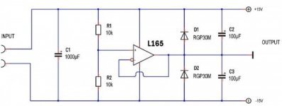
I have now spent nearly 4 days trying figure out a persisting problem with this L165 virtual earth circuit! No matter what i did, both the +/- voltages are quite assymetrical giving +11.84 & -12.08 or thereabout.
I even removed R3 & R4 as it was on an other variation of this circuit & it got worse! This particular reg. is a ST brand (Micro Electronics?). I also read elsewhere of d.i.yers experiencing the same problem with this particular device. I even built 3 seperate circuits, still the same problem persists on all of them. Could it be that this particular brand or batch is faulty?
Do any of you guys have any idea or suggestion as to what this problem might be due to or suggest a similar high current feedback amplifier(s), which can source at least 100mA?
Attachments
Last edited:
Ahh....just remembered something! Since none of the scheamtics show the dc by-pass caps, I too didn't include these in my circuit! Perhaps this is what triggering oscillation thereby causing this problem???
Can anyone spot a fatal mistake in the schmatic on #post 1 ? No prizes given though!
Can anyone spot a fatal mistake in the schmatic on #post 1 ? No prizes given though!
Attachments
Last edited:
How in-exact is it ?
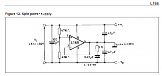
I notice the data sheet says -/+6 volts as a minimum and then shows an application using -/+4 volts. It also in two diagrams has the inputs mixed up. Look at your first post and post #3. The + and - inputs are reversed. Post #4 is electrically drawn correctly but I don't know if the pin numbers are correct
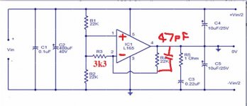
The unity gain follower uses a 1k resistor between the inputs (which is technique to reduce the available gain) and this points to stability issues. You could alter the circuit to do the same with two resistors and then add a small (say 47pf) cap across the "feedback" to kill any tendency to oscillate.
I notice the data sheet says -/+6 volts as a minimum and then shows an application using -/+4 volts. It also in two diagrams has the inputs mixed up. Look at your first post and post #3. The + and - inputs are reversed. Post #4 is electrically drawn correctly but I don't know if the pin numbers are correct
The unity gain follower uses a 1k resistor between the inputs (which is technique to reduce the available gain) and this points to stability issues. You could alter the circuit to do the same with two resistors and then add a small (say 47pf) cap across the "feedback" to kill any tendency to oscillate.
Why not add a small pot in series with your reference between R1 and R2 of 100 to 500 ohms and connect the wiper to pin 1. Bypass it with a cap for noise reduction then adjust for the output you want. The output voltage is going to be determined by how well matched the reference resistors are. If they are not perfect there will be an offset. This way you can adjust the offset out.
Transistormarkj, the circuit on #3 doesn't work & blowing fuses! I actually built this twice but with the same results both times! There are in fact 3-4 variations of this on the net! Only the #1 circuit works with the + rail 11.84v & the - at 12.08v from 24v supplied from 4 x 18640 batt. & through a buck booster. Tried with the dc caps too still no improvement. The voltages are constant but this annoying assymmetry! The resistors are matched of course! Yes, I did notice the wrong pin orientation & corrected it. I actually got the specs from ST Micro Electronic pages.
There's definitely something untowards going on either with this chip or the various circuits!
ST Micro
There's definitely something untowards going on either with this chip or the various circuits!
ST Micro
") with the changes...now reading +11.84 & -11.91!! Thank you...thank you..it helped a lot! but does this still mean high dc offset?
with the changes...now reading +11.84 & -11.91!! Thank you...thank you..it helped a lot! but does this still mean high dc offset?Unequal supplies have no effect on (for example) opamp circuitry. If you have +16 and -6 or -18 and +5 the DC offset of the circuitry is essentially unchanged.
The fact that the results have improved/altered possibly points to the original circuit oscillating. A scope check would really be needed to confirm that but the modified circuit should prevent any possibility of that happening. The values aren't critical. Also the 1 ohm and 0.22uf isn't strictly necessary or lets say if you want it then I would also add the same to the other rail too. Maybe increase the 1 ohm too.
The fact that the results have improved/altered possibly points to the original circuit oscillating. A scope check would really be needed to confirm that but the modified circuit should prevent any possibility of that happening. The values aren't critical. Also the 1 ohm and 0.22uf isn't strictly necessary or lets say if you want it then I would also add the same to the other rail too. Maybe increase the 1 ohm too.
This is the same technique applied to opamp circuitry,
http://www.diyaudio.com/forums/analog-line-level/196461-different-opamp-compensation-technique.html
http://www.diyaudio.com/forums/analog-line-level/196461-different-opamp-compensation-technique.html
Thank you indeed for the the link. I've now tested the circuit with various values of R3 which gave the following figures;
Resistor value +V -V
3k3........+11.84 - 11.91
4k7........+12.00 - 12.06
10k........+12.04 - 12.06
Higher the R3, better the symmetry
Higher the R3, increase in output voltages!
None of the data sheets give Imax (sink/source currents) for L165.I wonder why?
Resistor value +V -V
3k3........+11.84 - 11.91
4k7........+12.00 - 12.06
10k........+12.04 - 12.06
Higher the R3, better the symmetry
Higher the R3, increase in output voltages!
None of the data sheets give Imax (sink/source currents) for L165.I wonder why?
Last edited:
The source/sink current will be the max output current of the L165 which is around 3 amp.
The reason the output voltages vary slightly as the resistor is altered is partly because of slightly differing input bias currents (the tiny current that flows into or out of the two input pins) which cause a slight DC offset. That same problem affects ordinary opamps too. The other reason is that the L165 isn't a "precision" opamp, but neither is a cause of concern.
The reason the output voltages vary slightly as the resistor is altered is partly because of slightly differing input bias currents (the tiny current that flows into or out of the two input pins) which cause a slight DC offset. That same problem affects ordinary opamps too. The other reason is that the L165 isn't a "precision" opamp, but neither is a cause of concern.
No wonder that most C.F.B amplifier data sheets don't specify sink/source current! Then do you reckon using L165 to draw about 125mA is an overkill? The supply current for L165 is specified 40/60mA average/max @ +/-18v, which is quite high for a battry splitter IMO; My 3 prime concerns are heat,noise & battery drain.
I have a couple of LT1206 & BUF634 which are rated @ 250mA ....perhaps one of these is a better alternative? In any case I will try thes first with circuit & give you the results.
With regard to the circuit, I did move the output caps quite close to the pins, so perhaps this might have helped as well?
Thanks for your timely advice again! I will try the BUF634 as you've recommended. The only confusion is that on TI data... the splitter resistors are 10k, while "Tangent" design has used 220k! Why the difference & significance? Perhaps lesser current o/p with "Tangent's?
I actually started reading your link....very detailed, well over my head. Will read it a few times.
I actually started reading your link....very detailed, well over my head. Will read it a few times.
Last edited:
I've never used the BUF634 but I see the data sheets mentions a low bandwidth mode that gives reduced current consumption. That's what you want to use.
The resistors, well 20K total is 1.5ma at 30 volts, comparable with the IC consumption. No reason not to go higher... its something you would have to try. Go to high and the input bias current will alter (pull down) the voltage at the junction of the two resistors. I'd try 100K or 22K and see how it perform.
The resistors, well 20K total is 1.5ma at 30 volts, comparable with the IC consumption. No reason not to go higher... its something you would have to try. Go to high and the input bias current will alter (pull down) the voltage at the junction of the two resistors. I'd try 100K or 22K and see how it perform.
I tried the the BUF634 & found it to be more stable than L165 & was actually a doddle. However, I observed a few things which you may find interesting & perhaps give your take on.
1. Even with accurately matched resistors the - rail was a few mV higher on no load .
conditions.This increases with higher values & with a +/- voltages dropping
corrospondingly (10k,22k & 100k)
2. Choosing a slightly lower value for the + both rails gave exactly the
same voltages! Then after a few minutes on measuring the resistors I noticed the
lower value R too had increased to almost exactly the same value as the other R!
3. When connected to the load, the -rail increased by about -22mV compared to the
+ rail with the 10k R. This may have been due to imbalance in the load?
However, I didn't notice any increase in the dc offset as you had rightly assured. The BUF runs quite cool even on a very small heatsink.
Great it all seems to work OK.
It all sounds normal, the data sheet quotes an offset of typically -/+30 mv, 100mv worst case and variation with supply of 1mv/v
Higher resistor values mean that the current drawn by the input pin has a greater effect on the voltage at the resistor junction, and that current will almost certainly change with temperature. Just think of parallel resistors. If you used 100 ohms for the two then a variation in the current caused by a parallel 100K resistor makes little difference. Now imagaine if the resistors were 10K. It makes quite a difference now. The input current of the chip can be likened to the 10K except it will be a lot higher and variable in nature with temperature and supply
- Status
- This old topic is closed. If you want to reopen this topic, contact a moderator using the "Report Post" button.
- Home
- Amplifiers
- Power Supplies
- TROUBLE WITH THE L165!