Anyone have any ideas for some simple modifications to a CJ Walker CJ58 Turntable?
Does anyone out there have any experience of it? It's really cheaply built, but actually a lovely bit of design - so maybe room for improvement?
At the moment it's standard, but with no lid, no base, new feet, and a RB300 with an AT95E on the end of it. Looking for a bargain MC, but also considering unipivots, new plinth, better hardware, springs, etc...
It'd be cool to hear any ideas.
Sorry, I've just realised there are three Walker turnatables
I know of.
The round one - and a version of this with a plinth - both
have 3 point suspension and a T shaped MDF subchassis.
There is an older big squarish turntable that has a full armboard,
and uses if I remember correctly a H shaped subchassis and has
4 ! point suspension.
I think your model is the 3 point with the plinth, but not sure.
Mods to come once I know which one it is !
") / sreten.
/ sreten.
I know of.
The round one - and a version of this with a plinth - both
have 3 point suspension and a T shaped MDF subchassis.
There is an older big squarish turntable that has a full armboard,
and uses if I remember correctly a H shaped subchassis and has
4 ! point suspension.
I think your model is the 3 point with the plinth, but not sure.
Mods to come once I know which one it is !
/ sreten.I think you were right on just about everything. Mine is later and although it was cheaper than any of the others it was thought to be the best sounding at the time...
Three point suspension with two pieces of mdf(?) held together in a 'T' with staples. I've thought about using screws or glue instead, but I wonder whether the fact that they're decoupled actually works to damp resonance in the system (does that make sense?). It could easily be made more rigid.
The top part of the plinth is cut from a sheet of 12mm veneered fibreboard but the surround is chipboard with plastic veneer. horrible, and held together with staples.
The arm mounting is horrible too. It's not tall enough to be mounted directly on to the subchassis/armboard, so it's held in place by the mounting off one of those cheap(ish) mission arms.
The motor is a little noisy when it's running. I've seen those rubber sleeve things and baring kits on ebay but I'm not convinced... Maybe a home-brew D.C. motor and PSU?
Anyway, this has become a bit of an essay. The deck sounds great. Clean, and very 'musical' and 'right', but is lacking in dynamics, bass weight and treble definition. It's dusty, but gets a lot of use.
What do you reckon? I'm on a budget but have access to lots of secondhand bits and bobs.
Hi,
I'm very confident I can address your dynamics and definition
issues with cheap modifications based on the modifications
I've done to other turntables in the past.
Bass weight is a different issue - I do architectural bass grip -
to be further discussed because it has more to do with the
whole system.
A lot of use is what I like to hear !
I'm sorry but writing the reply is going to take longer than
I've available today - I expect to be able to write it tommorrow.
Frustrating - I know !
/sreten.
I'm very confident I can address your dynamics and definition
issues with cheap modifications based on the modifications
I've done to other turntables in the past.
Bass weight is a different issue - I do architectural bass grip -
to be further discussed because it has more to do with the
whole system.
A lot of use is what I like to hear !
I'm sorry but writing the reply is going to take longer than
I've available today - I expect to be able to write it tommorrow.
Frustrating - I know !
/sreten.I'll post some photos this evening.
Regarding proper alignment of the cartridge, I need to make a new arm board for the deck as the cut-out is in the wrong place. The cartridge is almost aligned... not quite right though until I re-mount the arm. I was wondering if gluing another piece of MDF on the existing armboard (need to raise the arm up as well) might add too much mass and unbalance the subchassis. What do you think? I could always go back to the old mission arm, but it's not great...
Regarding proper alignment of the cartridge, I need to make a new arm board for the deck as the cut-out is in the wrong place. The cartridge is almost aligned... not quite right though until I re-mount the arm. I was wondering if gluing another piece of MDF on the existing armboard (need to raise the arm up as well) might add too much mass and unbalance the subchassis. What do you think? I could always go back to the old mission arm, but it's not great...
modifications
I'll just note that i'm not into overengineered modications 'just because you can'.
The following is based upon being simple to do, and the high probability of being
maximally effective with the lowest probability of unexpected adverse side effects.
It is based on modifying over ten decent but inexpensive turntables to various degrees.
My current Vinyl player is a modified SystemDek IIX, Rega RB200, Ortorfon MC15 Super II.
**************************
Three point suspension with two pieces of mdf(?) held together in a 'T' with staples.
I've thought about using screws or glue instead, but I wonder whether the fact that
they're decoupled actually works to damp resonance in the system (does that make sense?).
It could easily be made more rigid.
**************************
Using PVA wood glue clamp and glue the subchassis together. Extend the the cutouts to
suit the Rega arm - which needs a longer spindle to arm distance than the Mission arm.
Obtain some aluminium sheeting - I'm assuming here its 0.5 to 0.6 mm thick.
The subchassis is reinforced top and bottom with 3 or 4 layers of aluminium.
The shape is an assymetric truncated triangle - say clearing the T junction by
1 cm on one side and 3cm on the other near the bearing, the assymetry to spread
resonances. Consequently two of the three suspension points are unaffected.
The aluminium layers and the subchassis are glued together using contact adhesive.
(The model used here is constrained layer damping)
We are talking the proper stuff here - usually in the sniffing cabinet -
do not use the wimpy water based stuff - (well I never have).
Using these adhesives is an art in itself - so ask for more details if you are not sure.
You'll need the cutouts in the aluminium layers for the bearing, the Rega arm and the
third suspension point.
Araldite the main bearing into its new position, don't use too much araldite as
its not critical, invert the subchassis and surround the bearing exit with araldite.
**************************
The top part of the plinth is cut from a sheet of 12mm veneered fibreboard but the surround
is chipboard with plastic veneer. horrible, and held together with staples.
**************************
Yes, vinyl had to be used for the surround so it could fold around all the edges.
If the vinyl is wood effect - I'd suggest spraying the whole turntable silk black.
And find a lid !
Building a new plinth is a possibility - but pointless in terms of sound quality.
**************************
The arm mounting is horrible too. It's not tall enough to be mounted directly on to the
subchassis/armboard, so it's held in place by the mounting off one of those cheap(ish)
mission arms.
**************************
I'll assume you have two Rega steel arm washers.
Go to a plumbers merchant and aquire a number of large nylon or similar plastic washers.
Use around 6mm of the plastic washers with the Rega steel washer and nut below the armboard.
Above the armboard with the other steel Rega washer they are used for hieght adjustment.
(I use a cut down felt mat between my platter and subplatter for fine height adjustment)
When you are finally happy, retorque the nut after a day or so.
The arm lead needs to be dressed, the easiest way to do this :
Put a single twist in the lead and attach it to the plinth so that its ~ in line
with the rotation of the subchassis around the main bearing.
**************************
The motor is a little noisy when it's running. I've seen those rubber sleeve things and
bearing kits on ebay but I'm not convinced... Maybe a home-brew D.C. motor and PSU?
**************************
DC motors, servo or not, had an appalling reputation in the heyday of vinyl.
I can't see what's changed.
On a subchassis turntable the motor should be solidly mounted.
The AC motor will make horrible grinding noises if its oil dries out.
Simply oiling the motor (top and bottom) will improve its performance no end.
For an 'improved' PSU for the AC motor checkout Neil McBrides Naim site,
and the Armegeddon clone. I haven't tried it, but if I did I would use a
much smaller transformer, the transformer used is IMO utterly ridiculous.
**************************
Ground Plane
*************************
I've found a proper groundplane is essential for low noise / hum.
The earthing of the Rega arm via its lead should be removed and a seperate earth
wire run back to the amplifier. All metal parts should be connected to this earth.
These are the arm, motor and subchassis layers.
The groundplane can be aluminium foil glued to hardboard, or aluminium sheet.
Steel sheet helps magnetically
- an easy way of damping metal groundplanes is self adhesive vinyl floor tiles.
Cutting out holes to access the suspension is fine.
**************************
Cartridge
**************************
Is utterly dominated by the arm and turntable its connected to.
However they determine the tonal balance of the turntable and the quality
of the treble if the arm isn't getting in the way, generally it does.
The last turntable I rebuilt was fitted with a relatively cheap cartridge,
but I can confidently say it would wipe the floor with an inferior turntable
fitted with the most expensive cartridge you could care to mention.
The cheap cartridge basically only lacked treble tracking resolution.
The tonal balance of the cartridge must suit the system.
Moving coils are simply not necessary for high quality.
To be further discussed.
Hiya,
Definately some real food for thought there... Here's a photo of the deck's guts. Sorry about the poor quality...
In answer to your question re springs, there is a whole roughly 1/2" in diameter through which the bolt passes. The spring mounts directly in a rebate in the subchassis, which surrounds the hole. The conical springs are held in place by circular rubber mounts which sit on the adjusting nuts. These rubber mounts have seen better days. Any idea on replacements?
The arm mount still poses some issues, and no, I don't have the rega washers, but I know the ones you mean (serrated). The arm has to be raised by so much that there'd be no room to get them on and tighten the nut properly. Are these washers important?
Attachments
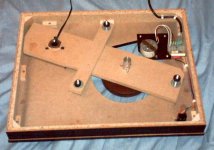
Very useful picture :
I thought it was very similar underneath to the round one but it isn't.
Need some time to ponder the innards.
The rega washers are 50mm diameter 3mm thick.
Using them would mean the centre of the plastic washers
wouldn't have to fit the Rega arm. By large washers I was
thinking something like 65/75mm diameter.
At least you can get the arm on !
/sreten.
I thought it was very similar underneath to the round one but it isn't.
Need some time to ponder the innards.
The rega washers are 50mm diameter 3mm thick.
Using them would mean the centre of the plastic washers
wouldn't have to fit the Rega arm. By large washers I was
thinking something like 65/75mm diameter.
At least you can get the arm on !
/sreten.Some things simpler but the arm is going to be tricky.
Looks like I need more info about the armboard, I want
to make sure you will be able to get the arm back on.
The three marks around the arm nut ? the attachment for the mission armbase ?
I can see an extra section of wood at the arm end of the subchassis.
How thick is this ? is it permanently attached ?
Does it protrude through the top plate or sit flat below a cutout ?
Is the section of subchassis in the top corner needed ?
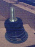
I'll need a better picture of the rubber mounts to suggest possible replacements.
How far clear of the top-plate is the platter (underneath to top plate) ?
/sreten.
Looks like I need more info about the armboard, I want
to make sure you will be able to get the arm back on.
The three marks around the arm nut ? the attachment for the mission armbase ?
I can see an extra section of wood at the arm end of the subchassis.
How thick is this ? is it permanently attached ?
Does it protrude through the top plate or sit flat below a cutout ?
Is the section of subchassis in the top corner needed ?
I'll need a better picture of the rubber mounts to suggest possible replacements.
How far clear of the top-plate is the platter (underneath to top plate) ?
/sreten.First of all - the arm mounting. Yes, there is an extra piece of wood attatched to the top of the subchassis (glued?) at the arm end. I'd say it's a 6mm piece of MDF. It sits below a cutout in the plinth. Presumably to raise the height to match the original mission arm - and look right throught the large cutout in the plinth. This does make it harder to set up the subchassis though as there's less clearance to the plinth top-plate.
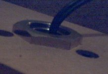
There is pretty much no thread at the arm base - see photo. The nut's half off as it is. The three marks are nuts for the allen key bolts that hold the original mission mount in place.
Beyond the arm mount, the extra length on the subchassis is needed cosmetically to blank the hole in the top plate of the plinth. A proper mount for the rega would be further along anyway. I could probably shave a bit off the end without spoiling the looks of the deck.
My original solution was to remove the extra piece of wood on top, cut out a large hole in the subchassis, and glue on a thick piece of mdf with a rega-sized hole in a stepped arrangement so that the top mount clears the plinth cutout, but leaves enough space underneath to allow the nut on the rega to be tightened. Hope I've explained that right...
Attachments
Now, other stuff...
The clearance from the platter to plinth top plate (with current set-up) is roughly 7mm. This couldn't be made any lower, because the arm would foul the plinth. Out of interest, both the platter and sub-platter are both made of a wood/resin-based composite (tufnol?) and the platter has a bonded felt mat.
Below is the best picture I can manage of the suspension mounts, which I can best describe as rubber washers with indentations moulded into their edge to guide the springs. This is the roughest one. Probably because it needs to be tightest to properly balance the sub-platter.
By the way, I have a spare motor, platter, sub-platter and bearing. I am considering building an all-new sub platter for this project... It might be easier in the long run.
Attachments
- Status
- This old topic is closed. If you want to reopen this topic, contact a moderator using the "Report Post" button.
- Home
- Source & Line
- Analogue Source
- CJ Walker Mods