I have a pair of BG RD50's that I am building a baffle for. They were working fine, but after using one of them to transfer the rivet location to the wood baffle for mounting them, it has no output. Now that I have done it - used a punch to tap on the rivets to mark the wood behind the them - not smart. I fear that I have loosened the connections to the aluminum ribbon. It measures none to very high resistance, intermittently. There are endcap covers at each end that look like they are riveted in place for access to the connections. Does anyone have experience or direction on a fix, for this self-inflicted problem? Thanks.
BG-50 Repaired!
I did get it fixed, though it was quite an ordeal. It doesn't look that pretty, but I have measured 3.9 ohms like the other driver and the output measures the same on HolmImpulse; so if it holds, I'd say it was a success. I'll post some pictures with some description in a week or so.
I did get it fixed, though it was quite an ordeal. It doesn't look that pretty, but I have measured 3.9 ohms like the other driver and the output measures the same on HolmImpulse; so if it holds, I'd say it was a success. I'll post some pictures with some description in a week or so.
Wrong way and better way
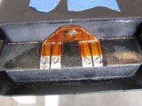
The attached pics show the non-terminal end of the driver after drilling out the rivet and what it looks like underneath. This is the end that was bad, though the other is the same, but had a PC board connection. The pic shows the aluminum foil conductor that is laminated to the diaphragm and the soldered connections to the copper wire that jumpers the ends of the aluminum together. The solder connections were loose - I could move them around. Don't try to re-solder them. It will melt the diaphragm and separate the aluminum foil. The first thing I tried was to clean up the corrosion inhibitor grease that was on the connections and coat with silver epoxy. This is not reliable, so after that failed, I was out of room on the connection side of the spacer that holds down the diaphragm. I then drilled a hole through the spacer, ran a fine insulated, braided copper wire and soldered it to some copper tape with conductive adhesive. I clamped the tape before removing the release paper next to where I soldered on the wire so the heat would not attack the adhesive. The tape was about 5/8" long that adhered to the aluminum diaphragm conductor. I smoothed it out with a pencil eraser. Also before putting the tape down, I made a little plastic tool, stuck 600 grit sand paper to the end of it and gently cleaned the aluminum and wiped with alcohol.
Before doing this I tested the tape's power handling by putting the tape on some aluminum foil and these two in series with my soldering gun. It handled the 140 watts of the gun pulling the trigger intermittently and continuously! This is the tape I used to build my electrostats. I have seen posts where people wonder if the adhesive side or the copper should go to the diaphragm. Based on what I found here - definitely use the adhesive side to conduct and adhere to the mylar.
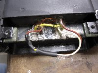
Back at the end of the copper tape wire I soldered it to other connections that did work out with the silver. Had I known how good the copper tape worked, I would have definitely started with it, like putting it directly over the soldered connections that were bad. I have quite a mess there, but I had nothing to lose. Now they sound great!
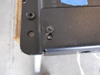
Since the covers were riveted, I tapped some small pieces of steel, epoxied in placed and used 4-40 flat head screws to hold the covers on.
The attached pics show the non-terminal end of the driver after drilling out the rivet and what it looks like underneath. This is the end that was bad, though the other is the same, but had a PC board connection. The pic shows the aluminum foil conductor that is laminated to the diaphragm and the soldered connections to the copper wire that jumpers the ends of the aluminum together. The solder connections were loose - I could move them around. Don't try to re-solder them. It will melt the diaphragm and separate the aluminum foil. The first thing I tried was to clean up the corrosion inhibitor grease that was on the connections and coat with silver epoxy. This is not reliable, so after that failed, I was out of room on the connection side of the spacer that holds down the diaphragm. I then drilled a hole through the spacer, ran a fine insulated, braided copper wire and soldered it to some copper tape with conductive adhesive. I clamped the tape before removing the release paper next to where I soldered on the wire so the heat would not attack the adhesive. The tape was about 5/8" long that adhered to the aluminum diaphragm conductor. I smoothed it out with a pencil eraser. Also before putting the tape down, I made a little plastic tool, stuck 600 grit sand paper to the end of it and gently cleaned the aluminum and wiped with alcohol.
Before doing this I tested the tape's power handling by putting the tape on some aluminum foil and these two in series with my soldering gun. It handled the 140 watts of the gun pulling the trigger intermittently and continuously! This is the tape I used to build my electrostats. I have seen posts where people wonder if the adhesive side or the copper should go to the diaphragm. Based on what I found here - definitely use the adhesive side to conduct and adhere to the mylar.
Back at the end of the copper tape wire I soldered it to other connections that did work out with the silver. Had I known how good the copper tape worked, I would have definitely started with it, like putting it directly over the soldered connections that were bad. I have quite a mess there, but I had nothing to lose. Now they sound great!
Since the covers were riveted, I tapped some small pieces of steel, epoxied in placed and used 4-40 flat head screws to hold the covers on.
Attachments
![IMG_0836[1].jpg](/community/data/attachments/331/331334-c6aa1656b3792909acce45550b1e9893.jpg)
Mine was definitely on the soldered end connections. I proved that by probing outside the connections and measured 1 ohm on each of the four legs.
I think if you were to make rounded, larger pads for your meter probes (to avoid poking through the membrane), you could isolate the break. Then clean the spot and put the copper tape over it.
I think if you were to make rounded, larger pads for your meter probes (to avoid poking through the membrane), you could isolate the break. Then clean the spot and put the copper tape over it.
Resurrecting this thread. I have been working on a set of Amazings with the twin 30" planar tweeters. One of the 30" sections is vibrating uncontrollably. Like the membranes have delaminated from the foil. Is there an adhesive that I can use to relaminate these pieces without damaging the mylar or the foil?
Thanks!
Thanks!
Resurrecting this thread. I have been working on a set of Amazings with the twin 30" planar tweeters. One of the 30" sections is vibrating uncontrollably. Like the membranes have delaminated from the foil. Is there an adhesive that I can use to relaminate these pieces without damaging the mylar or the foil?
Thanks!
trying again to see if anyone's got information to the above. Is there a place I can send this tweeter to have it laminated properly?
The amazing tweeters are full of issues.
I've heard of cases where the magnets got dislodged when the speakers were bumped, and yes several cases of rattling as well as broken continuity like mine.
See what you can find about making a new ribbon. If you can find a thin enough membrane, it could be your best bet. The rebuild charge for these is 650 per unit, you have 4 its gonna be 4 X that. And guess what, it will still be as unreliable on the other aspects. You bump it and you could have magnets jump to each other. There is also the question of magnets coming apart. Ceramic magnets that were cut with a billet shear are not the most stable of things.
Cool.
Srinath.
- Status
- This old topic is closed. If you want to reopen this topic, contact a moderator using the "Report Post" button.
- Home
- Loudspeakers
- Planars & Exotics
- BG RD50 Repair - no output