Here is my latest purpose built sub idea for a local club, I'd love to have some opinions as to whether I'm missing anything.
First some background info:
The room is two floors that make a 50'w x 40'D x 22' tall box, with a stage centered on the back wall of the bottom floor. There's a 3/4 wraparound balcony that is 10' deep on the sides and 20' deep in the front opposite the stage. each floor has full service bars occupying basically 5' of depth. The stage has 18.5" of internal height, it is 1/2 of an octagon, 8' deep, 16' wide. Nutshell: It's an acoustics clusterfuck.
Currently there are 2 EV QRx118s under the stage powered by a bridged QSC RMX2450.
The club regularly rents 4 CV T36/750 and 2 QSC PL236 to augment LF when they have import DJs, mostly EDM. This gets them plenty of bass on the lower level, but those boxes run out of gas on the lowest registers of the program material, and occupy 18 precious sq ft of their limited floor...additionally, the balcony mainly feels the LF through their feet.
(for those wondering, M/H support on lower level is 2 biamped EV QRx 212/75, and upper level has 2 EAW 5164, behind the EVs are 2 more of the EAW as sidefill)
So, the goals are to provide a flat stupid level of very deep LF in the lower level without decimating their floorspace, and to give the upper level some midbass/high sub support to balance the seismic disturbance it's floor will pass to the audience.
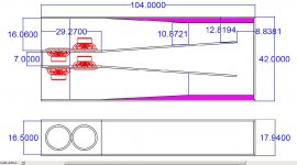
My proposed solution is 3 of the box described below. One centered under the stage, the other two standing against the wall on either side of the stage (obviously modified to have a side exit). They will each be loaded with 4 TCSounds Epic12 and powered by one channel of an FB10000Q (4 channels, 2100w/ch @ 4Ω, 2500 @ 2Ω). The current EV subs will go upstairs and run from the 4th channel of the Lab.
The pink wedges of filled space I thought I'd just make with pink styrofoam & then glass over, simple construction with extra rigidity as a bonus. I'm still trying to decide on a best way to make the shallow angle in l2-l3...maybe a butt joint with a lamination of glass on each side?
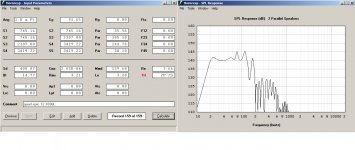
I'm showing the curve for just the 2 cabs that would be against the back wall with the amp at full output...
Thoughts?
First some background info:
The room is two floors that make a 50'w x 40'D x 22' tall box, with a stage centered on the back wall of the bottom floor. There's a 3/4 wraparound balcony that is 10' deep on the sides and 20' deep in the front opposite the stage. each floor has full service bars occupying basically 5' of depth. The stage has 18.5" of internal height, it is 1/2 of an octagon, 8' deep, 16' wide. Nutshell: It's an acoustics clusterfuck.
Currently there are 2 EV QRx118s under the stage powered by a bridged QSC RMX2450.
The club regularly rents 4 CV T36/750 and 2 QSC PL236 to augment LF when they have import DJs, mostly EDM. This gets them plenty of bass on the lower level, but those boxes run out of gas on the lowest registers of the program material, and occupy 18 precious sq ft of their limited floor...additionally, the balcony mainly feels the LF through their feet.
(for those wondering, M/H support on lower level is 2 biamped EV QRx 212/75, and upper level has 2 EAW 5164, behind the EVs are 2 more of the EAW as sidefill)
So, the goals are to provide a flat stupid level of very deep LF in the lower level without decimating their floorspace, and to give the upper level some midbass/high sub support to balance the seismic disturbance it's floor will pass to the audience.
My proposed solution is 3 of the box described below. One centered under the stage, the other two standing against the wall on either side of the stage (obviously modified to have a side exit). They will each be loaded with 4 TCSounds Epic12 and powered by one channel of an FB10000Q (4 channels, 2100w/ch @ 4Ω, 2500 @ 2Ω). The current EV subs will go upstairs and run from the 4th channel of the Lab.
The pink wedges of filled space I thought I'd just make with pink styrofoam & then glass over, simple construction with extra rigidity as a bonus. I'm still trying to decide on a best way to make the shallow angle in l2-l3...maybe a butt joint with a lamination of glass on each side?
I'm showing the curve for just the 2 cabs that would be against the back wall with the amp at full output...
Thoughts?
Attachments
Last edited:
if you use high densety foam(roof foam) its not neccesery to put glass over it.
ive used it for corner fillings in a bass horn.
i think the bass wil be epic")
edit/imo the differnce between foam or no foam wil be marginal,or a bit in favor of the no foam.
make s3 slightly bigger and see the differnce.
ive used it for corner fillings in a bass horn.
i think the bass wil be epic
edit/imo the differnce between foam or no foam wil be marginal,or a bit in favor of the no foam.
make s3 slightly bigger and see the differnce.
Last edited:
Looks sick.
- I don't think you're going to have enough grunt in the kick drum area 80-200hz between these and the EV tops. May have to consider a kick bin with these.
- How does a compareable bandpass horn or normal front loaded horn look vs. this? You will get better phase response and much cleaner requency extension up into the kick range.
- What sort of processor will you use to delay your tops to time align with these subs?
- Seems like you might be slightly underpowering these @ 4 ohms for each cabinet, 2000w rms rated, fed with an amp that maxes out at 2100w? I would prefer to see something capable of least 3000w RMS into each of these cabs.
- Why the epic 12? Why not a 15", and why not a pro driver?
Last edited:
The styrofoam idea seems like a ton of extra work, I'd simply make the cabinet trapezoidal if it needs that angle.The pink wedges of filled space I thought I'd just make with pink styrofoam & then glass over, simple construction with extra rigidity as a bonus. I'm still trying to decide on a best way to make the shallow angle in l2-l3...maybe a butt joint with a lamination of glass on each side?
Thoughts?
Looks like they will really hump down low!
Hi Trackzilla,
You should be able to get comparable performance using a 3-segment Hornresp model, save about 100L internal volume, and have an easier construction. Use lots of bracing. Don't worry too much about the peaks and valleys in the bottom of the passband, from looking at Danley's models it looks like plus minus 2-3dB should be fine.
Regards,
Thanks for the responses, my weekends are just one show after another, so I couldn't return here 'til today.
epa: I like the roof foam idea, I'll look into that. I agree the difference is nominal in constricting S3, but it seemed to bring up the 35 Hz-ish up by a dB or two particularly when I looked at the max response. It is a small enough difference that I'll likely try one with & one without & compare.
turbodawg: The room typically runs bands on Fri/Sat, and DJs (mostly EDM) on Tue/Thurs, Karaoke on Wed. As is stands before the proposed upgrades, the two EV 118 are the only house LF. They have proven to meet the clubs expectations for band use, we'll definitely be able to exceed that post upgrade. It looked to me that a front loaded horn would have to be way huge to get me down to 20Hz, any smaller would roll off, much like the T36 that we rent to them for the EDM shows (the house considers them enough, but they also seem to find it acceptable to kill one a month despite our best efforts to keep them appropriately limited & Lowpassed, I don't). House processing is a Presonus 24 ch board/DBX Zone Pro/EV DX38/Altodrive 2.4...so I'll have the processing horsepower to tweak the various subs discretely to make it all line up & tame the occasional spike. Power looked to me to be close enough as it's enough to bring the cabs to Xmax in the lowest registers, will physically fit in their rack (unfortunately also a consideration), and is inside the budget. I played with lots of drivers & models, did get something that was close to this with dual Lab15s, but it was going to take 6 cabinets, and more space from the club. I found with a bit of tweaking a similar result can be achieved with the Lab12 or the Dayton UM12-22. The TC just seemed to edge those two out as I played with the modelling.
weltersys: I hoped to keep the rectangular exterior for visual purposes, with the roof foam/no filling suggestion from epa, I think that got acceptably easy. I'm still not sure about how to easily accomplish the shallow bend between the baffle plate & the rest of l2-3.
mRgSr: I am a bit worried about that as well, I just couldn't wrap my head around how to define the measurements...so I guessed In my defense, I rationalized as follows: The cone on one side will provide extra space that the magnet on the other would somewhat more than fill. The thickness of the plywood would add a bit more back since the drivers are mounted from the other side (it goes the other way at S4). And armed with that, I just checked to make sure my predictions wouldn't go unacceptably ugly if S1, S2, & S4 were off by a little bit...I would love for someone to explain to me how to actually figure out the driver occlusion for real.
tb46: Hrmmmm...got a rough I can look at?
My limitations are pretty evil considering my objectives. The space beside the stage limits me to 42x90 due to bar proximity and balcony, and to fit under the stage we have to be less than 18" on the other box. I was going to accomplish the 90" dimension on those 2 cabinets by folding the baffle/mouth section 90 degrees & laminating additional ply to the exterior top, effectively making a small step along the wall at the edge of the stage out of it. Sonically, our target was defined by the output of the 4x T36 we rent to them, they hit 144dB at rated power in the midbass...I intend to extend basically that same output level all the way down so the EDM guys can break glassware instead of subs.
BTW: The bar has already put a 1/2" lip on the front of all of their shelves after the first show they rented rig from us...I told them to before, but they had to learn it the hard way.
epa: I like the roof foam idea, I'll look into that. I agree the difference is nominal in constricting S3, but it seemed to bring up the 35 Hz-ish up by a dB or two particularly when I looked at the max response. It is a small enough difference that I'll likely try one with & one without & compare.
turbodawg: The room typically runs bands on Fri/Sat, and DJs (mostly EDM) on Tue/Thurs, Karaoke on Wed. As is stands before the proposed upgrades, the two EV 118 are the only house LF. They have proven to meet the clubs expectations for band use, we'll definitely be able to exceed that post upgrade. It looked to me that a front loaded horn would have to be way huge to get me down to 20Hz, any smaller would roll off, much like the T36 that we rent to them for the EDM shows (the house considers them enough, but they also seem to find it acceptable to kill one a month despite our best efforts to keep them appropriately limited & Lowpassed, I don't). House processing is a Presonus 24 ch board/DBX Zone Pro/EV DX38/Altodrive 2.4...so I'll have the processing horsepower to tweak the various subs discretely to make it all line up & tame the occasional spike. Power looked to me to be close enough as it's enough to bring the cabs to Xmax in the lowest registers, will physically fit in their rack (unfortunately also a consideration), and is inside the budget. I played with lots of drivers & models, did get something that was close to this with dual Lab15s, but it was going to take 6 cabinets, and more space from the club. I found with a bit of tweaking a similar result can be achieved with the Lab12 or the Dayton UM12-22. The TC just seemed to edge those two out as I played with the modelling.
weltersys: I hoped to keep the rectangular exterior for visual purposes, with the roof foam/no filling suggestion from epa, I think that got acceptably easy. I'm still not sure about how to easily accomplish the shallow bend between the baffle plate & the rest of l2-3.
mRgSr: I am a bit worried about that as well, I just couldn't wrap my head around how to define the measurements...so I guessed
In my defense, I rationalized as follows: The cone on one side will provide extra space that the magnet on the other would somewhat more than fill. The thickness of the plywood would add a bit more back since the drivers are mounted from the other side (it goes the other way at S4). And armed with that, I just checked to make sure my predictions wouldn't go unacceptably ugly if S1, S2, & S4 were off by a little bit...I would love for someone to explain to me how to actually figure out the driver occlusion for real.tb46: Hrmmmm...got a rough I can look at?
My limitations are pretty evil considering my objectives. The space beside the stage limits me to 42x90 due to bar proximity and balcony, and to fit under the stage we have to be less than 18" on the other box. I was going to accomplish the 90" dimension on those 2 cabinets by folding the baffle/mouth section 90 degrees & laminating additional ply to the exterior top, effectively making a small step along the wall at the edge of the stage out of it. Sonically, our target was defined by the output of the 4x T36 we rent to them, they hit 144dB at rated power in the midbass...I intend to extend basically that same output level all the way down so the EDM guys can break glassware instead of subs.
BTW: The bar has already put a 1/2" lip on the front of all of their shelves after the first show they rented rig from us...I told them to before, but they had to learn it the hard way.
Last edited:
Here is my latest purpose built sub idea for a local club, I'd love to have some opinions as to whether I'm missing anything...
Thoughts?
I noticed this a few days ago but I didn't have time to really look until now. It appears you are missing a lot of things.
1. We don't usually sim in 1 pi unless we have a corner available. (Corner loading is technically .5 pi but you will never get the full theoretical benefit that the sim shows.) If you have a very solid concrete wall and the mouth is firing into the corner floor/wall junction you might justifiably use 1 pi but in this case (unless I'm mistaken) you don't have a really good case for 1 pi.
2. Your sim uses 91.65 volts. As shown, your sim appears to be about 4 mm past xmax with this amount of power.
3. The only way I can match your spl graph as shown is to run the sim and then use the multiple speakers tool to add 1 cab (for a total of 2 cabs). Since you are planning to use a total of 3 cabs it's really weird that you didn't show the results of 1 cab (as most people would) or 3 cabs.
4. One of your dimensions is 104 inches, which is longer than 8 feet. Plywood longer than 8 feet is expensive and sometimes hard to find. 104 inches is only 8 inches longer than 8 feet, so for 8 inches you are buying yourself a potential heap of trouble.
5. Dispersion (directivity) is going to be a mess if your subs are 16+ feet apart.
6. Using the same drivers and same overall cab size (net) it took me about 3 minutes to beat the snot out of your sim. If you get a bigger amp and assuming the drivers can handle the extra power I can beat it by quite a bit.
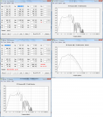
Graph 1 (line 1) - I redid your sim in 2 pi space and only enough power to hit xmax (1400 watts).
Graph 2 (line 1) - spl results for these inputs, 1 cab vs 3 cabs
Graph 3 (line 2) - my three minute front loaded horn for comparison - it's the same size as your tapped horn but it can take a boatload more power before it hits xmax
Graph 4 (line 2) - spl results for the flh, 1 cab vs 3 cabs
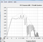
Graph 5 (line 3) - direct comparison of tapped horn vs flh, 3 cabs of each
It would take a bit of work to change the hpy/ex flh into par segments but I didn't want to spend more than 3 minutes on this.
Attachments
Last edited:
Just a guy,I
6. Using the same drivers and same overall cab size (net) it took me about 3 minutes to beat the snot out of your sim. If you get a bigger amp and assuming the drivers can handle the extra power I can beat it by quite a bit.
Graph 5 (line 3) - direct comparison of tapped horn vs flh, 3 cabs of each
The increase in sensitivity above 30 Hz the FLH shows would be a good thing.
Even though the sim shows double the power can be put in without exceeding Xmax, much of that increase would go to heat and power compression.
When things get "out of hand", most EDM drivers fail from thermal, not mechanical problems.
Since the TH already is around Pmax at Xmax, and with EDM one does not want to exceed Pmax, the FLH looks to be around + 2-3 dB in the 80 Hz range over the TH, a good improvement, though I'd be hard pressed to say that is "beating the snot out of" the TH sim.
Also, if using PP as the OP seems to want, one driver would be at a serious heat disadvantage in a FLH, the tiny chamber would be like an oven in a couple songs, reducing the +2-3 dB advantage further, real world might be only half that.
Art
Attachments
You bring up some good points, all of which I was going to address if the OP showed any interest. I was also going to bring up another point as well. Since the flh needs a much higher high pass (about 10 hz higher) that will take a bit away from the flh sim around tuning and the only way to get that back is even MORE power.
To address the power concerns head on, I've never burned a sub. Ever. Even when I try to reach pmax and xmax at the same time in my sims it ALWAYS sounds bad long before it burns. Even when I exceed pmax before hitting xmax in my sims it ALWAYS sounds bad before I have thermal issues. In other words, I've always had excursion issues and never thermal problems. Now if you have a clueless dj that keeps turning it up well past the point that it starts to sound bad that's another story completely...
My sim is shown at 3500 watts rms per cab (875 watts per driver). The drivers are rated at 500 rms (2000 peak) and I think they could handle the power I've shown them at with minimal thermal compression. As you pointed out awhile back, assuming fairly dynamic music the drivers only get a fraction of the amp's full output capability most of the time.
Chamber size in this design is 200 liters. This is almost 5x larger than the Labhorn rear chamber. This design has twice as many drivers though, so cut this larger design in half and then driver for driver it's almost 2.5x larger than the Labhorn rear chamber. To be painfully clear, the Lab has about 21 liters per driver and this design has 50 liters per driver. Also, this design is tuned almost an octave lower than the Lab, which means much more cone movement, which equates to a lot more fan action cooling the coils.
The Labhorn is obviously not the best example of a thermally controlled environment but compared to this design they are not even close. You have almost 50 percent more chamber PER DRIVER in this design compared to the Lab and a lot more cone movement to help cool the drivers. So I don't think calling the chamber "tiny" and "an oven" is really fair. Besides, the chamber could be increased by 25 liters without causing any problems but I didn't do that because I was trying to keep it the same size as the tapped horn sim presented in post #1. Also, the design could be tuned even lower than shown, requiring a much larger chamber if that was desired.
Even though I don't think thermal issues would be a problem I'm obviously not funding this and not paying for replacement drivers so it is good to make the OP aware of all this.
One final point. I don't know your definition of "beating the snot out of" but the sim I showed is 3 db higher at tuning and almost 10 db higher at certain spots above tuning. I don't see the thermal issues as being a large factor like you do, so IMO I did beat the snot out of it. Give me a bit more room (larger enclosure size limitation) and I could beat the snot out of it, kick it around for awhile, and then dance on it. Remember, I limited my enclosure size to the same size as the OP's tapped horn design and still beat it by a large margin in 3 minutes flat. Maybe my modesty leaves a bit to be desired but this isn't rocket science.
Last edited:
I checked to see if Josh at data-bass.com had tested this driver. Unfortunately he had not. The only 12 inch tc driver he had tested was the lmsr. I believe it's this one.
TC Sounds LMS-R 12" DVC Subwoofer 293-658
So as you can see the manufacturer's specs say it's rated for 1000 watts rms.
Data-bass.com did not actually state how many watts they tested this driver with on any page that I could find but they did measure Re at 4.15 ohms here:
Data-Bass
And measured spl with voltages up to 143 volts here (second graph - long term power compression):
Data-Bass
I used Hornresp to do the math for me since I'm very very bad at math.
143 volts at 4.15 ohms is very close to 5000 watts rms. As anyone might expect, there was significant power compression at this level.
But at 101 volts there was very minimal power compression. That's right around 2500 watts rms.
That's not so bad for a driver rated at 1000 watts rms. So if the little tc epic has anything in common with it's big lmsr brother you can see why I'm not too worried about power compression.
Last edited:
You may want to define the outside dimensions of your boxes.
Regards,
He's got all the dimensions in the first attached pic in post #1.
Hi just a guy,
Yes, he does, and then he changed things in Post #7. So, it would be nice to have some firm values to look at.
Regards,
Thanks, I was mostly focused on post #1 so I didn't notice any subsequent changes. I'll have to reread.
Anyway, if he's making changes, I'd suggest keeping the longest dimension at 96 inches so he can use regular 8 foot plywood.
... driver for driver it's almost 2.5x larger than the Labhorn rear chamber. To be painfully clear, the Lab has about 21 liters per driver and this design has 50 liters per driver.
I forgot to mention, this calculation assumes all 4 motors are in the rear chamber in my design. If he does do PPSL and has only 2 motors in the rear chamber, then those 2 motors would be sharing 200 liters (100 liters each), almost 5x more chamber size (per driver) than the Lab.
One other point that I forgot to mention is that I did not vet the chosen drivers for flh design, I just used the same drivers the OP used. Different drivers might yield even better results.
And measured spl with voltages up to 143 volts here (second graph - long term power compression):
Data-Bass
I just noticed this link doesn't lead to the right spot. You have to click the "multi-series charts" tab on this page and then the "long term power compression" graph is the second graph on that page. I don't think there's any way I can link directly to the correct page.
It would be much easier to edit the original post than create a new post just for this, but that's life at diyaudio, I guess.
- Status
- This old topic is closed. If you want to reopen this topic, contact a moderator using the "Report Post" button.
- Home
- Loudspeakers
- Subwoofers
- latest study in excess