Hi all,
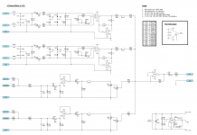
Following the simple two channel mixer, I have now drawn up a design for a basic four channel mixer. This version has two balanced XLR inputs with preamps (channels one and two) and two unbalanced stereo inputs (channels three and four). All channels need to go to an unbalanced output. As this will be used live on stage, a “popless” mute switch is required for all four channels.
I have attached the schematic and I was hoping people would be kind enough to critique the design.
The preamp stage for channels one and two is based upon the Dantimax ThatMic design with a few changes to the variable gain stage, the addition of an OPA137 opamp and the removal of the phantom power supply circuit (dynamic mics will be used). The OPA137 is to drive down the DC output to 0V as per the recommended design for the INA217 (as seen here – page 7).
For channels three and four, 0V DC output is achieved using C303/R306 and C403/R406 and is taken from Douglas Self’s Small Signal Audio Design (p. 341).
Are these methods the best to get DC output to 0V – thus avoiding pops and clicks when the channel is muted? If not, what changes should I make?
Are there any other goofs I have made (quite likely being me!)?
Sorry for the questions again, but I would really appreciate any help.
Thanks very much!
Attachments

Hi all,
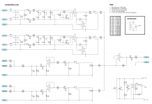
I just edited the attachment – I had missed off a resistor part code. The file attached to this post is the correct one.
If anyone has any feedback on my design I’d really appreciate it.
Thanks very much again.
I just edited the attachment – I had missed off a resistor part code. The file attached to this post is the correct one.
If anyone has any feedback on my design I’d really appreciate it.
Thanks very much again.
Attachments
I had a quick look at your schematic:
1) Unless you plan to add phantom power, the input caps C104, 105, 204 and 205 (and also the output caps C303, 403 and 501) should not be polarized.
2) Why are ther 2 pots on the line-level outputs (VR301, 401)?
3) Why C103, 203?
4) A601 could be replaced with an inexpensive op-amp and I would add a capacitor from pin 3 to ground.
Cheers, E
Hi Mickeymoose,
Thanks very much for looking at my schematic, I really appreciate it.")
I am certain phantom power will not be added in the future as this project will be used only with dynamic mics. I have therefore changed these caps to bi-polarized versions as per your recommendation (please see new schematic attached).
I have probably drawn this poorly! VR301 is one pot as is VR401. These are dual gang pots and I have tried to show both “gangs” on the schematic. I selected to use a dual gang linear pot to get closer to a true logarithmic control. I have read that using a linear pot in this way provides superior performance to that of a standard “log” pot. I read this information from Rod Elliott’s “Better Volume (and Balance) Controls” page (see figure 5).
This was a design feature of the Dantimax ThatMic pre-amp design on which this is based. I must say I did not understand this feature but as I have plenty of space for this inside the enclosure I plan to use for this project, I decided to retain it the design.
I have added a 100uF cap from pin 3 to ground (please see new schematic). Is there a particular opamp you would recommend as a replacement for the LT1206? Budget concerns are not really an issue with this project so I don’t mind paying for the LT1206.
Thanks very much again for looking at my design. I really appreciate the help.
Thanks very much for looking at my schematic, I really appreciate it.
1) Unless you plan to add phantom power, the input caps C104, 105, 204 and 205 (and also the output caps C303, 403 and 501) should not be polarized.
I am certain phantom power will not be added in the future as this project will be used only with dynamic mics. I have therefore changed these caps to bi-polarized versions as per your recommendation (please see new schematic attached).
2) Why are ther 2 pots on the line-level outputs (VR301, 401)?
I have probably drawn this poorly! VR301 is one pot as is VR401. These are dual gang pots and I have tried to show both “gangs” on the schematic. I selected to use a dual gang linear pot to get closer to a true logarithmic control. I have read that using a linear pot in this way provides superior performance to that of a standard “log” pot. I read this information from Rod Elliott’s “Better Volume (and Balance) Controls” page (see figure 5).
3) Why C103, 203?
This was a design feature of the Dantimax ThatMic pre-amp design on which this is based. I must say I did not understand this feature but as I have plenty of space for this inside the enclosure I plan to use for this project, I decided to retain it the design.
4) A601 could be replaced with an inexpensive op-amp and I would add a capacitor from pin 3 to ground.
I have added a 100uF cap from pin 3 to ground (please see new schematic). Is there a particular opamp you would recommend as a replacement for the LT1206? Budget concerns are not really an issue with this project so I don’t mind paying for the LT1206.
Thanks very much again for looking at my design. I really appreciate the help.
Attachments

Hi Dufflefan:
I had a quick look at Elliott's website. I believe he writes about hifi systems and a balance control married to a level control. I'll have another look when time permits, but I believe a log pot would serve you better. Or use a linear pot in the feedback loop of the amplifier (goto Shure.com | Global Home | Choose Your Region and serch for the M267 schematic and look at the U201 circuit)
Also, you will have some level shifting (and propably some popping noises) when SW101 and 201 are activated. This than becomes a active selector, not a mixer. All 4 circuits should be permanently attached to the mixing bus. If you need switches, do not use toggle switches, but self-cleaning slide switches!
Cheers, E
When you get to laying out the pcb take great care with grounding.
The audio ground and power supply grounds should meet at one place at the power connector on the pcb.
I mixed power supply and audio grounding on a pcb and ended up with massive hum.
Despite lots of cuts and links I couldn't get the hum to stop.
So I designed a new pcb with power and audio grounds connected once at the power connector.
Hi Mickeymoose,
Thanks very much for the heads up on volume controls. I’ll check out the M267 schematic and see what I can do. If, for whatever reason, that doesn’t provide a solution I’ll use a log pot for simplicity.
As for the level shifting, do you think it would be possible, rather than muting the signals and causing pops, to use a low pass filter to essentially keep the signal, but render it inaudible (filtering to below 1Hz for example)? Would this avoid popping? Unfortunately the application of this project requires instant muting for each individual channel. Am I correct in thinking popping is not a problem with SW301 & SW401 as it eliminated by C303/R306 and C403/R406 respectively?
Sorry for all the questions!
Hi Nigelwright,
Thanks for the warning about grounding. I’ll keep this mind when I get to the PCB layout.
Thank you both again - I greatly appreciate you taking the time to help me out.
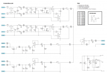
Sometimes I get lazy! Put a 100 ohm resistor on the outputs of A301 and A401. Than the 4 switches to ground to short the outputs for muting. The op-amps should be able to handle that and you can use cheap toggle switches for this. Alternately, use analog IC switches especially designed for this. Level shifts will be minimal. E
Put a 100 ohm resistor on the outputs of A301 and A401.
Hi again Mickeymoose,
Thanks for all your help - this is my last question I promise!!
I have added the 100 ohm resistors (R308 and R408) and attached a revised schematic. Have I placed these correctly or should they be placed after DC drain resistors R306/R406 and before the switches (so as to isolate shunt capacitance)?
I have also decided to keep things simple and use a log pot for VR301 and VR401.
Thanks a lot once again for your assistance.
Dufflefan.
Hi Speedskater,
I’m very sorry but I don’t know exactly which elements of the schematic you are referring to. It is quite likely I might have drawn something poorly!
Attachments
Dufflefan:
You missunderstood me. The switch should place a short between the 100R and the 10kR to ground, otherwise you still have the level shift when an input is muted.
When all channels are active the 10kR are in parallel and set the gain of A501 with R501 (10k:4) if one channel is off it is 10kR:3.
Your ground symbols are OK. It is just the way your program does it and identifies the circuit nodes.
Overall gain is also affected by the settings of VR301 and 401. Maybe they are better placed at the inputs of A301 and 401 or go with the scheme of the M267.
And: keep asking! E
Hi again Mickeymoose,
My apologies for the misunderstanding!
I have moved the volume controls to the inputs of A301 and A401 as suggested.
I have also relocated the 100R resistors (R308/R408) to the end of the outputs before the 10K resistors. Between these I have inserted the switches which divert the signal to ground when muted.
I have attached a new schematic showing these changes. I hope this is correct!
Thanks again for the guidance, it is very much appreciated!
My apologies for the misunderstanding!
I have moved the volume controls to the inputs of A301 and A401 as suggested.
I have also relocated the 100R resistors (R308/R408) to the end of the outputs before the 10K resistors. Between these I have inserted the switches which divert the signal to ground when muted.
I have attached a new schematic showing these changes. I hope this is correct!
And: keep asking! E
Thanks again for the guidance, it is very much appreciated!
Attachments
Dufflefan:
Your current swithing (muting) arrangement will cause gain changes when the switch is activated.
What I meant: Connect the 100R to the 10kR. The switch onto this junction, the other side to ground. Muted when the switch is closed. This is not the best, but the cheapest way. I prefer a semiconductor solution. E
Dufflefan:
Your current swithing (muting) arrangement will cause gain changes when the switch is activated.
What I meant: Connect the 100R to the 10kR. The switch onto this junction, the other side to ground. Muted when the switch is closed. This is not the best, but the cheapest way. I prefer a semiconductor solution. E
Hi Mickeymoose,
I've got it now!
Sorry for the misunderstandings. I think I'll stick with the switches for muting purposes but next time I'll read up on semiconductor muting. I haven't read enough on the subject as yet but I will certainly be considering it for my next project once I've read more.
Thanks again for all the assistance. When you're learning with these things having such help is a huge benefit. It is greatly appreciated.
Dufflefan.
Hi Speedskater,
If I've understood correctly, I think you're referring to parts FB101, FB102, FB201 and FB202. If so, these are ferrite beads rather than ground symbols. I'll work on making the symbol a little clearer for next time!
I'd like to disagree with Mickeymoose on the change of gain with channel volumes and mute switches; on a high z mixing bus, this would be true, but on a virtual earth ultra low z bus like this there will be no change. Just a tiny change in noise levels, insignificant.
As a user (rather than designer) of mixers since op amps were not good enough for quality audio (my first mixers were designed round vacuum tubes), I've got certain habits, like separating the channel pot from the input gain, and putting a master volume so that different sensitivity power amps could be used with reasonable levels on the input pots (if A501 is compensated for zero gain, increase R 501 to 47k and put a 47k potentiometer – no, I suppose that's a rheostat, technically - round it in parallel).
Warning (not that you can do anything about it); once upon a time one could assume that mixing the two sides of the stereo into mono would give an acceptable balance. Older mixing engineers like myself always checked the mix in mono, in case it went across AM radio or televisions.
Newer producers, knowing their products are going to be distributed in mp3 and listened to on phones, find it more impressive to put in antiphase information, ignoring compatibility entirely, which can make for some pretty weird balances in mono. As I say, nothing you can do about it.
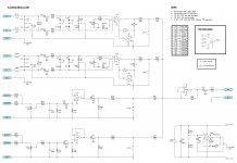
No it's the circuit ground symbols to which I refer. I fear that you plan to connect them to the XLR jack's pin #1.
Hi Speedskater,
Apologies for the confusion! I understand now. If I am correct this brings up the “Pin 1 Problem” which I have read about on the forum and elsewhere. I have heard differing opinions on whether or not to connect pin 1 to chassis ground or audio ground.
I had indeed intended to connect pin 1 of the XLRs (channels 1 and 2) to audio signal ground. My idea was to have audio signal ground for channels 1, 2, 3, 4 and the output jack all connected with only the power supply virtual ground connected to the chassis. However, thanks to your warning I have now altered the grounding system as shown in the attached schematic.
My design is now as follows:
Channels 1 and 2: Pin 1 of XLR connections to chassis ground.
Channels 3 and 4: Sleeve of TRS jacks to audio ground.
Output Jack (Mono/TS socket) to audio ground.
Virtual Ground of Power Supply to chassis ground.
Would this work ok? I can’t see that I have connected any ground loops with this setup but then again I am learning all the time!
Thanks very much for the help, I really appreciate it.
Dufflefan.
I'd like to disagree with Mickeymoose on the change of gain with channel volumes and mute switches; on a high z mixing bus, this would be true, but on a virtual earth ultra low z bus like this there will be no change. Just a tiny change in noise levels, insignificant.
Thanks for looking at the schematic. Having made the changes as per the recommendations of Mickeymoose and Speedskater, I am confident the design has been improved. It is satisfying to know however that my first design wasn’t too far off being ok. Something I can’t say expected so thanks for the comments!
As a user (rather than designer) of mixers since op amps were not good enough for quality audio (my first mixers were designed round vacuum tubes), I've got certain habits, like separating the channel pot from the input gain, and putting a master volume so that different sensitivity power amps could be used with reasonable levels on the input pots (if A501 is compensated for zero gain, increase R 501 to 47k and put a 47k potentiometer – no, I suppose that's a rheostat, technically - round it in parallel).
This is very interesting – a long time in the future, when I am more experienced, I hope to design valve amplifiers so this is useful to know. As I know which devices will be plugged into this mixer (and it is very unlikely these will change), I will retain the volume controls as per the current design to keep things simple.
Warning (not that you can do anything about it); once upon a time one could assume that mixing the two sides of the stereo into mono would give an acceptable balance. Older mixing engineers like myself always checked the mix in mono, in case it went across AM radio or televisions. Newer producers, knowing their products are going to be distributed in mp3 and listened to on phones, find it more impressive to put in antiphase information, ignoring compatibility entirely, which can make for some pretty weird balances in mono. As I say, nothing you can do about it.
Thanks for the information about mono balance and anti-phasing regarding modern recordings. Although there is nothing I can do, it is still very interesting to learn!
Attachments
- Status
- This old topic is closed. If you want to reopen this topic, contact a moderator using the "Report Post" button.
- Home
- Design & Build
- Construction Tips
- 4 Channel Mixer Design Critique Please?