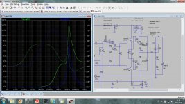
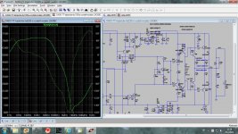
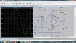
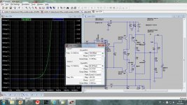
I simulated output impedance of two of my power amps, TT amp and LittleGem, in both cases before and after an output inductor.
This has leaded me to a conclusion that output inductor has an additional function beside to protect an amp against capacitive loads.
Long loudspeaker wires can pickup electromagnetic disturbances, and the loudspeaker drivers generate EMI and we don’t want that all this enter the amp, but to minimize it.
Some audio designer are against use of the output inductor in power amp, but in my opinion there is more advantage then disadvantage to use it.
I am using the output inductor in all my amps, but in JLH MOSFET amp were is used 0.22 ohm resistor instead.
From the simulation could be seen that output disturbances are suppressed from from 50 dB(LittleGem- double EF) up to 70 dB(TT amp, TRIPLE EF).
To this should be added closed loop gain(28 dB in my case) to get the level of output disturbances suppression at a GNFB input.
Did I get it right??
dado
Attachments
-
 LittleGem-output impedance-b.jpg221 KB · Views: 1,284
 -
 TT-amp output suppression.jpg236.5 KB · Views: 226
 -
 TT-amp-output impedance-b.jpg243.1 KB · Views: 1,080
 -
 TT-amp-output impedance.jpg232.2 KB · Views: 1,126
 -
 LittleGem-output suppression.jpg211.7 KB · Views: 1,151
 -
 LittleGem-output impedance.jpg214.5 KB · Views: 1,200
I think that protection against capacitive loads would not be the primary function as much as forming a barrier between the antenae (speaker wires) feeding RF ingress into the input stage via the feedback loop. Typically this coil is located at the speaker terminals of the amp enclosure, while the Zobel should be close to the output stage.
few uH series L are included in amps, explained by the designers as isolating the output stage from potentially destabilizing C load
possible RF ingress isolation has be recognized as a possible side effect, its also been shown how to rearrage Zobel components to improve the RF filter aspect
all you have to do is read "coventional" audio amp design books, articles by Self, Cherry, Cordell
possible RF ingress isolation has be recognized as a possible side effect, its also been shown how to rearrage Zobel components to improve the RF filter aspect
all you have to do is read "coventional" audio amp design books, articles by Self, Cherry, Cordell
RF rejection of alternate Zobel?
Well, Self is completely dismissive of any alternate connection of the Zobel after the inductor. It looks like a deliberate snub of Cherry's work.
But Cherry's article in Electronics World July 1997 doesn't provide any analysis of RF rejection in his proposed alternatives.
Bob Cordell's book is the best on the subject but there is still no real analysis.
Intuitively I expect that the Zobel after the inductor would have better rejection but I would like to check that.
Have I missed a quantitative analysis?
And thanks to Dadod for his post. RF rejection becomes even more important with some advanced feedback compensation methods so this is very useful.
Best wishes
David
Last edited:
few uH series L are included in amps, explained by the designers as isolating the output stage from potentially destabilizing C load
possible RF ingress isolation has be recognized as a possible side effect, its also been shown how to rearrage Zobel components to improve the RF filter aspect
all you have to do is read "coventional" audio amp design books, articles by Self, Cherry, Cordell
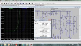
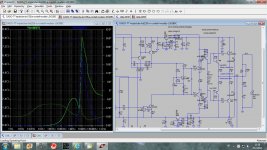
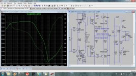
I have all those books, but a role of the zobel and series inductance is not so well explained nor simulated. Next simulation is with added zobel after series L and the load is electrical model of a single speaker unit ia sealed box(from Self book). I don't see any differences with previous simulations. Still very good suppression in the audio band but a low dip at 7MHz. Main reason for this dip is a sharp increase of the power amp's output impedance at that frequency.
dado
Attachments
Hi Dadod, we cross-posted fairly similar comments.
In your simulation of the downstream Zobel you can leave out the resistor in series with the Zobel capacitor (R15). The inductor damper resistor provides sufficient resistance I think. This should improve the rejection.
Best wishes
David
In your simulation of the downstream Zobel you can leave out the resistor in series with the Zobel capacitor (R15). The inductor damper resistor provides sufficient resistance I think. This should improve the rejection.
Best wishes
David
Hi Dadod, we cross-posted fairly similar comments.
In your simulation of the downstream Zobel you can leave out the resistor in series with the Zobel capacitor (R15). The inductor damper resistor provides sufficient resistance I think. This should improve the rejection.
Best wishes
David
David, no, it didn't. With no downstream zobel the result is the same, so in my simulation second zobel does not show any improvement in RF rejection.
BR Damir
Attachments

David, no, it didn't. With no downstream zobel the result is the same, so in my simulation second zobel does not show any improvement in RF rejection.
BR Damir
I don't understand why not, but that's why we check.
Thank you. I need to think about it.
Best wishes
David.
I don't understand why not, but that's why we check.
Thank you. I need to think about it.
Best wishes
David.
Could be that my simulation is not good enough, that's why I presented it here to get comments and suggestion.
BR Damir
Intuitively I expect that the Zobel after the inductor would have better rejection but I would like to check that.
Have I missed a quantitative analysis?.
The same intuition tells me that for HF rejection it work better
if connected before the inductance since it form a high frequency
damped L + RC circuit , seen from the speaker cables as being
the generator/antenna.
The same intuition tells me that for HF rejection it work better
if connected before the inductance since it form a high frequency
damped L + RC circuit , seen from the speaker cables as being
the generator/antenna.
I expected that the .1uF outboard Zobel capacitor with no series resistor would have an impedance of less than 1 ohm from 1.6 MHz upwards and that would short RFI pretty well. The inboard Zobel needs a series resistor so would be less effective. But RF behaviour is often not simple and my naive intuition is incorrect. So I check.
And at frequencies > about 16 Mhz we need transmission line theory to do it properly. We have entered the world of the cable fanatics.

Best wishes
David
Interesting topic, I agree that neither the Self or Cordell books treat this topic with enough analysis or present a deeper understanding of all the implications.
My 2 cents is that the zobel following the inductor would better attenuate pickup with the rationale that the amps output impedance would (depending on its bandwidth) form a second filter, and there is no limiting resistor right at the output.
It might be easier to see if you just plot the voltage at the amp output node.
Also I would think you need some cable / load capacitance (main rationale for the inductor in the first place) in the simulation to better see the effects of all the combined impedances.
Lastly I would expect some pickup susceptibility to common mode so using a dual inductor and a chassis shunt capacitor with a common mode choke right at the output to be beneficial.
Thanks
-Antonio
Last edited:
Interesting topic, I agree that neither the Self or Cordell books treat this topic with enough analysis or present a deeper understanding of all the implications.
My 2 cents is that the zobel following the inductor would better attenuate pickup with the rationale that the amps output impedance would (depending on its bandwidth) form a second filter, and there is no limiting resistor right at the output.
It might be easier to see if you just plot the voltage at the amp output node.
Also I would think you need some cable / load capacitance (main rationale for the inductor in the first place) in the simulation to better see the effects of all the combined impedances.
Lastly I would expect some pickup susceptibility to common mode so using a dual inductor and a chassis shunt capacitor with a common mode choke right at the output to be beneficial.
Thanks
-Antonio
Thanks Antonio for your suggestions.
As one picture says more then thousend words, please put some circuit here, or even better a simulation.
Here is zip file with my TT-amp and last simulation, please be free to use it for further simulations.
BR Damir
Attachments
I have seen numerous designs without an output inductor and not seen any problems with that. In practice I haven't seen any problems.
RF pickup usually comes in the front end and is killed by an RC filter.
Sometimes RF can get injected if the zero volts line is not connected to earth.
I have had terrible trouble with an MP3 player that has no earth and picks up loads of RF.
If I connect a CD player or PC that is earthed there is no problem.
Thanks Antonio for your suggestions.
As one picture says more then thousend words, please put some circuit here, or even better a simulation.
Here is zip file with my TT-amp and last simulation, please be free to use it for further simulations.
BR Damir
Damir
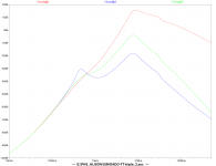
I've attached the corresponding voltage at the amp output resulting from your applied current. I dont think I managed to mess up your schematic (LTSpice Newbee). The red trace is with the Zobel at the amp output, the blue is with the capacitor at the output of the inductor. The green is just a quick compromise by having a full RC at the inductor output.
My past efforts have been to insure amplifier (especially output stage) stability, and thus just accept any side benefit of noise susceptibility reduction. A dual L just puts another L on the ground side.
Adding a common mode choke is just one or two turns of both output and return through a lossy ferrite toroid, works best if there is a shunt capacitor from the ground side to chassis, but this can introduce some grounds loops and even short out the return portion of the common (or differential) coupled inductor if the grounds are not handled accordingly.
Hope this helps
-Antonio
Attachments
Damir
I've attached the corresponding voltage at the amp output resulting from your applied current. I dont think I managed to mess up your schematic (LTSpice Newbee). The red trace is with the Zobel at the amp output, the blue is with the capacitor at the output of the inductor. The green is just a quick compromise by having a full RC at the inductor output.
My past efforts have been to insure amplifier (especially output stage) stability, and thus just accept any side benefit of noise susceptibility reduction. A dual L just puts another L on the ground side.
Adding a common mode choke is just one or two turns of both output and return through a lossy ferrite toroid, works best if there is a shunt capacitor from the ground side to chassis, but this can introduce some grounds loops and even short out the return portion of the common (or differential) coupled inductor if the grounds are not handled accordingly.
Hope this helps
-Antonio
Antonio,
If you devide that voltage with the current I1 and set the vertical scale to linear you will get the amp output impedance in ohm(miliohm).
I am trying to get difference between output impedance after and before the inductor to see value of the suppression of the garbage coming from the loudspeaker side.
I would not use ferrite at the output.
Damir
Member
Joined 2009
Paid Member
Antonio,
If you devide that voltage with the current I1 and set the vertical scale to linear you will get the amp output impedance in ohm(miliohm).
I am trying to get difference between output impedance after and before the inductor to see value of the suppression of the garbage coming from the loudspeaker side.
I would not use ferrite at the output.
Damir
To clarify, the voltage on the attached plot was Vout (as defined in your schematic) at the Amps output (before any rc's or inductors), so dividing it by I1 wont give you the Amps impedance.
You are not alone in avoiding ferrites, a dual air core will provide some common mode impedance (limited to ~6 ohms with the parallel R's and roll off with capacitance across the windings and resistors). I havent heard or measured a detrimental effect with common mode ferrites but my hearing isnt that great and I can't measure to the levels needed to show any iff effect.
Thanks
-Antonio
Well, Self is completely dismissive of any alternate connection of the Zobel after the inductor. It looks like a deliberate snub of Cherry's work.
But Cherry's article in Electronics World July 1997 doesn't provide any analysis of RF rejection in his proposed alternatives.
Bob Cordell's book is the best on the subject but there is still no real analysis.
Intuitively I expect that the Zobel after the inductor would have better rejection but I would like to check that.
Have I missed a quantitative analysis?
And thanks to Dadod for his post. RF rejection becomes even more important with some advanced feedback compensation methods so this is very useful.
Best wishes
David
Hi Dave,
Yes, the inductor thing and where to put the Zobel can be a point of controversey and maybe even some art.
I always recommend an inductor, even if it is fairly small. Amplifiers with unknown capacitive loads (or, effectively unterminated transmission line cables) can sometimes oscillate in brief bursts that may not be seen, but which may affect the sound. Without some decoupling, as provided by the inductor, it is difficult to get an amplifier to be unconditionally stable for nearly arbitrary loads, especially given the wide variation in operating points of the output stages as they go through an infinite variety of combinations of current and voltage. Even 1uH shunted by about 2 ohms can make a big difference.
The Zobel is very important to the stability of the usual EF output stage, and should be very close to the output stage transistors, with a well-controlled local return to signal ground. It wants to provide good resistive damping to very high frequencies, especially with fast output transistors. I even believe in what I call distributed Zobel networks in the output stage, when a plurality of small Zobels effectively in parallel is physically distributed across the output stage. Then the individual zobels can be smaller and less inductive. Then there is no need for big-wattage, non-inductive power resistors for the Zobel.
I also prefer to have a Zobel on the speaker side of the inductor, and located at or near the amplifier output terminals. We thus end up with a sort of pi output network. This can help the EMI situation and sometimes to some extent the possible speaker cable mis-termination concern. The key to recognizing the possible value of this is to realize that there is often some wiring inductance in the signal path from the output stage to the speaker terminals. Doug may regard this as over-kill, citing the damping effect already there as a result of the resistor across the inductor. The Zobel need not necessarily be big.
Also bear in mind that star grounding can make the return ground path at the speaker terminals be very different at high frequencies than the signal ground present at the output stage. A Zobel at each end mitigates any effects of this difference at high frequencies, damping the line to BOTH grounds.
You can tell that I like Zobels. They tend to help things behave at those high frequencies where there is some magic and layout sensitivity.
Finally, if you really want to be sure, put a Zobel at the speaker - at the far end of the speaker cable. I am not the first to advocate this, and I think some speaker cable manufacturers build this in. This helps make sure that the far end of the speaker cable is at least somewhat terminated at the far end (loudspeakers can look inductive at HF, even when there is a resistive L-pad in the tweeter circuit). While it is certainly true that speaker cables of reasonable length do not act like transmission lines at audio frequencies (and certainly need not be properly terminated at audio frequencies), the transmission line effects that can begin to emerge in the 1 MHz region can in some cases act to de-stabilize an amplifier.
I suspect that there are many amplifiers out there that may sound different merely because they are not unconditionally stable, and they may be issuing subtle parasitic bursts of oscillation in different ways. Similarly, different speaker cables connected to a marginally-stable amplifier may cause the sound to be different by altering the way in which the amplifier is mis-behaving.
Cheers,
Bob
It's odd that the output inductor has always been about 1uH, from the days of 2n3055 onwards. You would expect the value to have dropped to 100nH with modern transistors and FETs. Too high a value will be above its self resonance at problem frequencies.
When you talk about RF ingress, back in the 70s that meant amateur HF and CB. These days the sources are mostly above 1GHz
When you talk about RF ingress, back in the 70s that meant amateur HF and CB. These days the sources are mostly above 1GHz
- Status
- This old topic is closed. If you want to reopen this topic, contact a moderator using the "Report Post" button.
- Home
- Amplifiers
- Solid State
- Output inductor in power amps - pro and con