

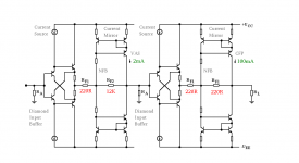
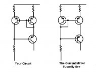
Nope, I don't think that this current mirror will give you gain.
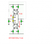
Take the top portion.
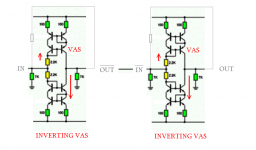
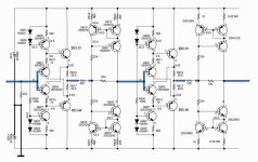
If the base of the transistor close to the "VAS" label starts to go negative, the emitter starts to go negative.
Then the base of the transistor on the left goes negative and tries to pull more current (in a positive direction) from the connection that is trying to pull the "VAS" transistor negative...with gain.
It looks like a current source that is supposed to be independent of drive...the added resistors.
Please explain how this is supposed to work.
I'm baffled.
")
Take the top portion.
If the base of the transistor close to the "VAS" label starts to go negative, the emitter starts to go negative.
Then the base of the transistor on the left goes negative and tries to pull more current (in a positive direction) from the connection that is trying to pull the "VAS" transistor negative...with gain.
It looks like a current source that is supposed to be independent of drive...the added resistors.
Please explain how this is supposed to work.
I'm baffled.

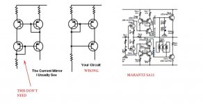
see now
the confusion stems from the fact that the fourth diode-connected bipolar not need
see also this pdf
Categorized Schematics and Service Manuals for free download
the confusion stems from the fact that the fourth diode-connected bipolar not need
see also this pdf
Categorized Schematics and Service Manuals for free download
Attachments
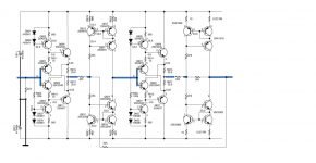
Is this the schematic Stee....is it correct...have you checked?
What is the supply voltage (much less than 80V?) and the stand by current?
Power supply filtering... how big the capacitance you suggest?
What is the impedance you suggest?
What is the level to input you suggest?
Is this amplifier complete?.... or we need and extra circuit to correct off set?
The use of BD139/140 said to me, once again, that you are good..... it is alike someone that is replacing a ball bearing of an automobile with a hammer or a proper adequated, correct tool.... this transistor choice show to me you use the correct tool... easy to detect this stuff... easy this way....people that does not use correct tool or do not know what is the correct tool use some other models and have not courage to choice something from the seventies..even being the best transistor ever made for drivers position.
I will simulate it...if good in simulation i will build.... good to me is low offset, flat to 5 hertz, no triangle wave before 200 kilohertz (low level input) and THD smaller than 0.05% (fourier).... so, my demmanda are easy to achieve and ever amplifier can do that....if good amplifier naturally.
Probably will be smashed as i gonna compared to my best amplifier...but if yours win..then i will post it here.
If mine win...i will say nothing..no one will never know if i have build it or not... so, this will not harm your name and will not bother you...i will not even let YOU know.
BUT...if not operates... wrong schematic, wrong values....then i will spit fire on you fratello.
Ahahahahahah!
I am happy.... the old fellow here had received visit from the family that came from 3 thousand kilometers south.... a bunch of Italian succession from the Danesi group.
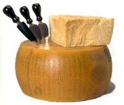
La signora nella foto cucina una bistecca impanata meravigliosa .... la moda milano
The woman you see in the right side cooks a beautifull steak that is tradition in Italy, the Parmezian steak (cheese, tomato juice over the pre coocked and baked cow steak)
regards,
Carlos
What is the supply voltage (much less than 80V?) and the stand by current?
Power supply filtering... how big the capacitance you suggest?
What is the impedance you suggest?
What is the level to input you suggest?
Is this amplifier complete?.... or we need and extra circuit to correct off set?
The use of BD139/140 said to me, once again, that you are good..... it is alike someone that is replacing a ball bearing of an automobile with a hammer or a proper adequated, correct tool.... this transistor choice show to me you use the correct tool... easy to detect this stuff... easy this way....people that does not use correct tool or do not know what is the correct tool use some other models and have not courage to choice something from the seventies..even being the best transistor ever made for drivers position.
I will simulate it...if good in simulation i will build.... good to me is low offset, flat to 5 hertz, no triangle wave before 200 kilohertz (low level input) and THD smaller than 0.05% (fourier).... so, my demmanda are easy to achieve and ever amplifier can do that....if good amplifier naturally.
Probably will be smashed as i gonna compared to my best amplifier...but if yours win..then i will post it here.
If mine win...i will say nothing..no one will never know if i have build it or not... so, this will not harm your name and will not bother you...i will not even let YOU know.
BUT...if not operates... wrong schematic, wrong values....then i will spit fire on you fratello.
Ahahahahahah!
I am happy.... the old fellow here had received visit from the family that came from 3 thousand kilometers south.... a bunch of Italian succession from the Danesi group.
La signora nella foto cucina una bistecca impanata meravigliosa .... la moda milano
The woman you see in the right side cooks a beautifull steak that is tradition in Italy, the Parmezian steak (cheese, tomato juice over the pre coocked and baked cow steak)
regards,
Carlos
Attachments


Last edited:
Amarna Optimum
Hello Carlos!
I'm glad you like the project
I have not tried it yet
also because it is evolving
with integrated buffer - to avoid another CCS pair
BD139/140 are really complementary (completely identical)
so it is better to use an output stage EF because the gain is unity and
power-bipolar gains are very different (PNP / NPN)
if you can simulate we can complete the design together
when I use two switching power supplies from 24V
are good because they have no noise
you can temporarily ignore the input buffer diamond
and begin to feel like playing the stage with voltage gain
we call it "alla Parmigiana"
Attachments
No thanks...i am already developing an amplifier and busy
I like it but now i know it needs development...i want to try something ready, built and tested..something from you..but simulated, with prototype assembled, tested, photographed and published, filmed and with all data informed, simulation results and so on.
I do not want to develop or help to develop other amplifier as i am already doing it and at same time helping the Dx Super A thread in several foruns, including mine one and the Dx Supply in several foruns too.
If was ready to go...with complete schematic without any kind of add on, and built, and tested..then i would give a shot on it...but this way i wll not do it because no time to do that.
I do think you are good on ideas..but you do not put your stuff in practice...this is a pity..we alway perceive a lack of something... a real pity, as your ideas are very interesting and unusual.
If you remember i have already assembled something you sent pcboards.... resulted with big offset and high harmonic distortion...so, was experimental.... i man rich or ideas in poor about action...a pity, we would be much more happy having you doing the whole job.
Parmigiana.... i have got it..... Parmigiano Regiano.... delicious cheese..the best!
thanks,
Carlos
Attachments
Last edited:
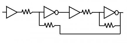
carlos, the first stage is often known as a diamond circuit.. works quite well and i have used that as a headphone amplifier - really just to provide drive current as my soundcard outputs 2V RMS but with not a lot of current... so it needs no gain as 2V RMS into 32 ohms load would deafen anyone quickly
It is run mostly in class A, for the small wattage needed by headphones this is OK.. but I use TO-220 output transistors here (MJE15032/3) - because I had them already. I would not like to think how inefficient it would be as a power amp!
I have also seen the diamond circuit used as a predriver in a power amp.. but the output stage is still standard EF-type class AB.
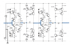
I'm not convinced the second Wilson mirror stage has any benefits. What gives me further doubt as to the credibility, is that the main schematic Stee shows is a straight cut and paste out of a Marantz service manual, then edit a bit.
It is run mostly in class A, for the small wattage needed by headphones this is OK.. but I use TO-220 output transistors here (MJE15032/3) - because I had them already. I would not like to think how inefficient it would be as a power amp!
I have also seen the diamond circuit used as a predriver in a power amp.. but the output stage is still standard EF-type class AB.
I'm not convinced the second Wilson mirror stage has any benefits. What gives me further doubt as to the credibility, is that the main schematic Stee shows is a straight cut and paste out of a Marantz service manual, then edit a bit.
- Status
- This old topic is closed. If you want to reopen this topic, contact a moderator using the "Report Post" button.
- Home
- Amplifiers
- Solid State
- Amarna Sun - a new amplifier design