Hello.
I am having a problem which I am unable to resolve myself because of my lack of electronic knowledge.
I've build an objective2 amp and the left channel is not working. I can only hear loud "boom" noise when switching the amp on or off. Right channel is working OK.
I am measuring about 13v of DC on this channel's output (measured from P2).
I've already build 2 O2s in the past and I've never experienced similar problem.
Does anyone know what the problem might be? I don't know much about electronic stuff so I have no idea what to do.
Sorry for my english")
I am having a problem which I am unable to resolve myself because of my lack of electronic knowledge.
I've build an objective2 amp and the left channel is not working. I can only hear loud "boom" noise when switching the amp on or off. Right channel is working OK.
I am measuring about 13v of DC on this channel's output (measured from P2).
I've already build 2 O2s in the past and I've never experienced similar problem.
Does anyone know what the problem might be? I don't know much about electronic stuff so I have no idea what to do.
Sorry for my english
Hello....
I am having a problem which I am unable to resolve myself because of my lack of electronic knowledge.
Sorry for my english
List your O2 rel. querries on this thread-
http://www.diyaudio.com/forums/head...ective2-o2-headphone-amp-diy-project-309.html
Chk the input socket, it might be faulty or dry soldered.
Use one end of i/p pin & chk for continuity of the i/p socket(blue)
I've build an objective2 amp and the left channel is not working. I can only hear loud "boom" noise when switching the amp on or off. Right channel is working OK.
I am measuring about 13v of DC on this channel's output (measured from P2).
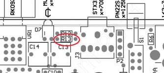
Try reheating the solder connections on R13, even if they look perfectly good.
Attachments
Hello.
I am measuring about 13v of DC on this channel's output (measured from P2).
Sorry for my english
I missed that one-
WARNING: don't connect your HD800 yet. 13 VDC is too much. List the issue on http://www.diyaudio.com/forums/head...eadphone-amp-diy-project-310.html#post3360698
I checked it. It's all ok.Chk the input socket, it might be faulty or dry soldered.
Use one end of i/p pin & chk for continuity of the i/p socket(blue)
Done. It didn't help.Try reheating the solder connections on R13, even if they look perfectly good.
I did follow the NwAvGuy's trobule shooting guide once more and here are the results.
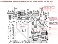
At Initial DIY Testing section I am failing Check The Raw DC Voltages part. Here are the results:
An externally hosted image should be here but it was not working when we last tested it.
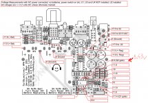
After that I jumped to Troubleshooting Problems section and I think there is something wrong at Negative Unregulated Supply part. This is what I got:
An externally hosted image should be here but it was not working when we last tested it.
Anymore ideas?
Last edited:
At Initial DIY Testing section I am failing Check The Raw DC Voltages part.
Yep, that is the other thing that will cause the problem, one power supply rail missing. No luck on viewing your images - first comes up the size of a postage stamp and I can't get the second to open at all - but check the voltage between ground (the metal shell of the gain switch) to pin 4 of one of the NJM4556 output chips (U3 or U4). Then measure between ground and pin 8. Be very careful not to short between the pins with the meter probe.
You should be getting close to -12Vdc on pin 4 and +12Vdc on pin 8 with the AC adaptor plugged in and the O2 turned on. If one of those voltages is missing, do the same tests between ground and pins 4 and 8 of U2, the NJM2068. If you get +/-12Vdc there but are missing one voltage on the output chips then one of your mosfets is not turning on.
Last edited:
I've attached the files that were currupted in previous post.
U3 - Pin4 = -16.61V
U3 - Pin8 = 11.71V
U4 - Pin4 = -16.63V
U4 - Pin8 = 11.71V
but check the voltage between ground (the metal shell of the gain switch) to pin 4 of one of the NJM4556 output chips (U3 or U4).
U3 - Pin4 = -16.61V
U3 - Pin8 = 11.71V
U4 - Pin4 = -16.63V
U4 - Pin8 = 11.71V
Attachments
I've attached the files that were currupted in previous post.
U3 - Pin4 = -16.61V
U3 - Pin8 = 11.71V
U4 - Pin4 = -16.63V
U4 - Pin8 = 11.71V
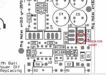
Those -16.6Vdc numbers on the Pin4's are a problem. Check the voltage from the banded end of diode D5 to ground (metal shell of gain switch) and see what you get. Should be -12.0Vdc +/- 0.3Vdc or so. If you are getting -16.6Vdc then either your negative voltage regulator (U6) is shorted, or more likely you have a solder bridge between the input and output pins on U6. On that chip (MC7912) the input and output pins are right next to each other and would be easy to short.
Use a magnifying glass to check - I've found it is nearly impossible to see a short there without using one.
Edit: looks like sofaspud and I were composing at the same time - and we agree on where your problem is.
See what you find there.Attachments
Last edited:
So the values are in normal
I was wondering about that! It didn't match up with the voltages in your diagram.
OK, about all the leaves is a bad NJM4556 chip. Try swapping U3 and U4 and see if the problem moves to the other channel. If so, that is the bad chip.
- Status
- This old topic is closed. If you want to reopen this topic, contact a moderator using the "Report Post" button.
- Home
- Amplifiers
- Solid State
- Objective2 - one channel doesn't work