Hi All,
I'm new to this forum and I have a new speaker project !
A few words about myself. I live in Paris, France. I'm 30, married and a child.
I'm an engineer and I like: creating stuff and listening to music...
This is what brought me to DIY audio.
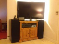
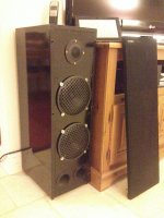
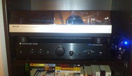
Two years ago, I completed my first speaker project, with which I'm not really satisfied today... I want to start something better. It is a two-way speaker based on 2 Monacor SPH-176 woofers and a 1 Monacor DT-254 tweeter. I have a Sherwood PM-9805 Vinyle, Yamaha A-S700 and Cambridge Audio A500.
There are several problems with my current setup:
- Sound is too directional and doesn't fill the room, specially the high frequencies which are too close to the ground level. I need to sit down in the direction of the speaker to hear them loud.
- It sounds like the sound is lacking mid-range. The bass are blurry and the tweeter is ok but the mid-range is absent. The spectrum doesn't sound linear.
- Not enough power
- Don't look good
So, now I would like to have a 3-way speaker and to make it more fun, I decided to use only French loudspeakers. This is why I named my project "The French Touch":
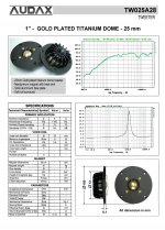
- 1 tweeter: Audax TW025A28, 8 Ohms, 94dB, 70 WRMS
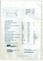
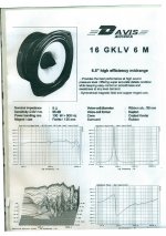
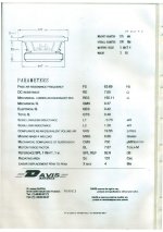
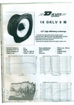
- 1 midrange: Davis Acoustics 16GKLV6M, 6.5", 8 Ohms, 95dB, 130 WRMS
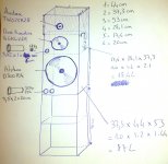
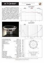
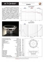
- 1 sub: Atohm D300P04, 12", 4 Ohms, 91dB, 200W RMS
I have attached the plan of the speaker. Sorry for the metric system...
I would like to add two shelfs at the bottom of the speaker, in order for the tweeter to be higher to the ceiling. I don't know if it's a good idea. It doesn't look good... In any case I need an idea to put my speakers higher than just putting them on the floor.
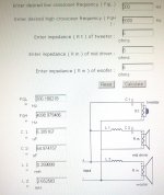
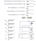
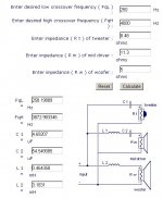
I intend to use a first order passive filter with the following layout:
- Tweeter : 5kHz - 20kHz
- Midrange : 300Hz - 5kHz
- Sub : 20Hz - 300Hz
I have attached the values of the components for the filter.
I intend to post my progress on this new project, here.
Because I have very limited budget and time, I will have to distribute the building phase over at least 6 months...
I'm new to this forum and I have a new speaker project !
A few words about myself. I live in Paris, France. I'm 30, married and a child.
I'm an engineer and I like: creating stuff and listening to music...
This is what brought me to DIY audio.
Two years ago, I completed my first speaker project, with which I'm not really satisfied today... I want to start something better. It is a two-way speaker based on 2 Monacor SPH-176 woofers and a 1 Monacor DT-254 tweeter. I have a Sherwood PM-9805 Vinyle, Yamaha A-S700 and Cambridge Audio A500.
There are several problems with my current setup:
- Sound is too directional and doesn't fill the room, specially the high frequencies which are too close to the ground level. I need to sit down in the direction of the speaker to hear them loud.
- It sounds like the sound is lacking mid-range. The bass are blurry and the tweeter is ok but the mid-range is absent. The spectrum doesn't sound linear.
- Not enough power
- Don't look good
So, now I would like to have a 3-way speaker and to make it more fun, I decided to use only French loudspeakers. This is why I named my project "The French Touch":
- 1 tweeter: Audax TW025A28, 8 Ohms, 94dB, 70 WRMS
- 1 midrange: Davis Acoustics 16GKLV6M, 6.5", 8 Ohms, 95dB, 130 WRMS
- 1 sub: Atohm D300P04, 12", 4 Ohms, 91dB, 200W RMS
I have attached the plan of the speaker. Sorry for the metric system...
I would like to add two shelfs at the bottom of the speaker, in order for the tweeter to be higher to the ceiling. I don't know if it's a good idea. It doesn't look good... In any case I need an idea to put my speakers higher than just putting them on the floor.
I intend to use a first order passive filter with the following layout:
- Tweeter : 5kHz - 20kHz
- Midrange : 300Hz - 5kHz
- Sub : 20Hz - 300Hz
I have attached the values of the components for the filter.
I intend to post my progress on this new project, here.
Because I have very limited budget and time, I will have to distribute the building phase over at least 6 months...
Attachments
Last edited:
re: "Sorry for the metric system..." - don't be, only colonials who don't don't know how to have a proper revolution use anything else...
Re: your crossover, it's too simple, a kevlar cone on the mid & the tweeter are going to demand something more than a simple 1st order xover to sound good,
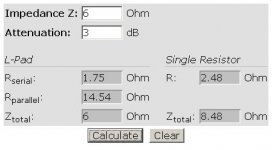
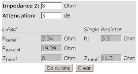
& you need to think about the relative sensitivities of the drivers - the mid & tweeter will need some padding: L pad calculator - attenuation dB damping impedance decibel loudspeaker speaker voltage divider - sengpielaudio Sengpiel Berlin
tweeter height - should usually be at ear level
Re: your crossover, it's too simple, a kevlar cone on the mid & the tweeter are going to demand something more than a simple 1st order xover to sound good,
& you need to think about the relative sensitivities of the drivers - the mid & tweeter will need some padding: L pad calculator - attenuation dB damping impedance decibel loudspeaker speaker voltage divider - sengpielaudio Sengpiel Berlin
tweeter height - should usually be at ear level
Usually, you try and get the tweeter at ear level when you are sitting down listening. So, stands. I would not integrate them. Just my choice. A 12 inch three way should be easy to make as a floor stander.
Being an engineer, I am sure you know textbook crossovers are darn near useless. Crossovers need to deal with the phase, position offset, comb effects from not being coaxial, cabinet edge diffraction, baffle step, efficiency differences, their inductance, mechanical rolloff, breakup modes, and the list goes on.
What background reading have you done before approaching this project?
Tid-bits: With a 300 crossover, you may be able to deal with baffle step with just level adjustments to the mid-range and tweeter. No network. But with first order crossovers, maybe not. Sometimes just shifting the woofer LP frequency down a little can pull it off.
I am really skeptical about the 5K first order on the mid. The tweeter will LOVE it. I know nothing about the Davis drivers, so I am just guessing. They may need come notch filters, and maybe a Zobel. Don't know until you see. I have not found any mid larger than 3 inches that can do 5K first order cleanly.
Why do you intend to use a tuned chamber for the mid? At 300 crossover, you are a couple octaves away from the resonance, so a sealed chamber that is "obviously" large enough would be fine.
It is current wisdom to put the ports on the rear of the chamber to minimize mid-range bleed ( reflections out the port. )
The rigidity of the box is important. One trick I liked was to make the mid-range chamber tie the front and back together. Brace and chamber all in one.
That should give you enough food for thought for a day.
Re: your crossover, it's too simple, a kevlar cone on the mid & the tweeter are going to demand something more than a simple 1st order xover to sound good,
& you need to think about the relative sensitivities of the drivers - the mid & tweeter will need some padding: L pad calculator - attenuation dB damping impedance decibel loudspeaker speaker voltage divider - sengpielaudio Sengpiel Berlin
Thanks !
In fact, I was hesitating about using this filter instead:
Visaton HW 3/130 NG - 8 Ohm
It includes this Lpad attenuation that you talked about for the mid and the tweeter.
But it is built for a 8 Ohm Sub. Mine is a 4 Ohms.
Perhaps I can add a 4 Ohms resistance in cascade with the sub ?
Is this filter powerful enough (180W) ?
If I switch to a second or third order, I would prefer to buy it rather than build it because the price difference increases with the component quantity...
tweeter height - should usually be at ear level
I usually listen to music just standing or moving around in the room. I like changing all the time the track, listening to particular parts, etc. etc. This is why I would like to have the tweeter quite high.
Being an engineer, I am sure you know textbook crossovers are darn near useless. Crossovers need to deal with the phase, position offset, comb effects from not being coaxial, cabinet edge diffraction, baffle step, efficiency differences, their inductance, mechanical rolloff, breakup modes, and the list goes on.
What background reading have you done before approaching this project?
Let's say that I have a generic education in electrical engineering.
I know about filters but mainly from a mathematical point of view.
I have very limited experience in applying filters theory to practical cases.
In particular, I don't know how far I need to care for each of those criteria that you mentioned.
I have read a few articles/DIYtutorials on the internet. What I have seen very often in those sites is that finding a mathematical answer to the perfect filter for a given set of loudspeakers is almost impossible. Most of the people say that they make some tests using different filters...
Tid-bits: With a 300 crossover, you may be able to deal with baffle step with just level adjustments to the mid-range and tweeter. No network. But with first order crossovers, maybe not. Sometimes just shifting the woofer LP frequency down a little can pull it off.
Ok, I didn't know about baffle diffraction step.
Will read that and come back later :
http://www.diyaudio.com/forums/multi-way/56769-when-use-baffle-step-compensation.html
Baffle Step Compensation
Baffle Diffraction Step
bafflestep
The Sub can hardly go above 300Hz because at this point the impedance is going above 10 Ohms...
I could choose 200Hz and leave the mid in the tuned chamber...
I have put in attachment the parameters of the loudspeakers.I am really skeptical about the 5K first order on the mid. The tweeter will LOVE it. I know nothing about the Davis drivers, so I am just guessing. They may need come notch filters, and maybe a Zobel. Don't know until you see. I have not found any mid larger than 3 inches that can do 5K first order cleanly.
I tried to simulate the closed chamber for the mid in WinISD. The -3db frequency is 150Hz. Isn't it too close to the first order xover cut-off ?Why do you intend to use a tuned chamber for the mid? At 300 crossover, you are a couple octaves away from the resonance, so a sealed chamber that is "obviously" large enough would be fine.
Ok, didn't know that. I will make the change on my plan. Thanks.It is current wisdom to put the ports on the rear of the chamber to minimize mid-range bleed ( reflections out the port. )
Is it possible to put the ports on the left/right of the chamber ?
Thanks !The rigidity of the box is important. One trick I liked was to make the mid-range chamber tie the front and back together. Brace and chamber all in one.
")
I wanted to keep my speaker as a single box.
It took me a while to find out a solution for two tuned chambers with the same width and completely different loudspeakers.
Attachments
a pre-built crossover won't match the characteristics of your drivers, for best sound, a crossover needs to be design specifically for the drivers you're using.
This is because the impedance values "8" &"4" ohms are the nominal impedance of the drivers - the actual impedance varies with frequency, so the xover needs to be designed for the actual impedance at the frequency the crossover is working at...
Re: the tweeter problem, another way to approach this is to use a tweeter with good wide dispersion characteristics e.g. SEAS 22TFF
Perhaps I can add a 4 Ohms resistance in cascade with the sub ?
Is this filter powerful enough (180W) ?
You will need a ~180 W power resistor.Let's say that I have a generic education in electrical engineering.
There are many engineers committing mistakes...
A pre-built crossover won't match the characteristics of your drivers, for best sound, a crossover needs to be design specifically for the drivers you're using.
This is because the impedance values "8" &"4" ohms are the nominal impedance of the drivers - the actual impedance varies with frequency, so the xover needs to be designed for the actual impedance at the frequency the crossover is working at...
I agree. A filter will not behave the same on each speaker setup. It needs to be designed specifically.
In theory, we should integrate the actual impedance curve in the filter computation. But I think this is a very complex computation only possible to make through simulation software and difficult to double-check in theory... The phase also, I am not sure what is the perceptible limit in the temporal shift between the speakers. Basically this is why I don't want to use complex filters. Simple is always better, right ?
I think using the average impedance value of the speaker on the working frequency range should be a good start. If the cutoff is correctly chosen, on the working frequency range the impedance of the speaker should be stable enough and have a trustable average value
.Re: the tweeter problem, another way to approach this is to use a tweeter with good wide dispersion characteristics e.g. SEAS 22TFF
I would like to keep it with "made in France" loudspeakers
It is the spirit of my projet
How can I check the dispersion characteristics of my audax tweeter ? (except listening to it ?)
Ok, but if I put a 4 Ohm resitor in cascade with my 4 Ohm loudspeaker, it will behave like an 8 Ohm loudspeaker from a filter point of view. But I will loose half the power of my amplifier in the resistor !You will need a ~180 W power resistor.
Yes, but very few accept itThere are many engineers committing mistakes...
Tid-bits: With a 300 crossover, you may be able to deal with baffle step with just level adjustments to the mid-range and tweeter. No network. But with first order crossovers, maybe not. Sometimes just shifting the woofer LP frequency down a little can pull it off.
Ok, I read about baffle step and given my baffle width, mine should occur at 115/Wb = 115/0.373 = 308 Hz with 3 to 6 dB loss in the sub.
My sub is already 3dB less sensitive than the mid and the tweeter. In the end, taking into account the bafle step I have a difference of at least 6dB between my Sub and my mid/tweeter. Happily this bafle step falls exactly at the cutoff frequency of my xover. If I want to attenuate my mid and tweeter I can add a resistor in parallel or in cascade. For example an 8 Ohm resistor in cascade to attenuate a 6dB.
But it's frustrating to add a pure resistance to my mid and tweeter !! They
Hi yov,
To design a crossover I think it's better to simulate it.
You can find measures of the Davis 16 on part express :
Davis 16gklv6m 6-1/2" Kevlar Midbass 297-568
A simulation tool wich can be good as a first try is PCD :
Loudspeaker Design Software
You should also take a look at the Davis MV15 crossover :
I see one problem on your design, with a passive crossover the woofer is not enough sensitive.
Attachments
Since you have engineering training, you will not have too much trouble learning how to use simulation software and measurement hardware/software. Since you are using expensive drivers, I think you can afford a calibrated microphone and USB interface/preamp (~130 Euro). It will be best if you also make a cable or buy a device to measure impedance, although you can trace the mfg. curves with the spltrace program for impedance instead and do okay (the ported midrange would be a problem, though). I suggest you do this right .
.
Last edited:
hmmm, the kevlar driver is smoother than I thought it would be, if this graph is to be trusted you may get away with 1st order: http://www.parts-express.com/pdf/297-568.pdf
Based on those impedance plots you were just talking abouthmmm, the kevlar driver is smoother than I thought it would be, if this graph is to be trusted you may get away with 1st order: http://www.parts-express.com/pdf/297-568.pdf
, the Davis driver starts to break up around 1.2kHz, and without heavy smoothing on the graph, it probably looks a bit nasty above that.Yup, you waste a lot of power padding the mid and tweeter. That's how it works.
You are going in the right direction. Remember, the most valuable measurement tool is your ears. All the rest of our equipment is to make it easier and quicker to identify problems. Sims can be helpful, but the don't do the work for you. You still have to understand what they are telling you and make the decisions yourself. There is only one right answer in speaker building: "It depends". At least when we mess up a speaker metric to inch measurement, we don't miss Mars, and when we totally mess up a crossover, the roof does not collapse. We enjoy "safe" engineering.
I prefer sealed enclosed for my mids because it helps the transient response. If you could do CSD (Cumulative Spectral Decay) measurements, you will see that sealed chambers damp the driver at and below it's resonance far better. Plug the mid into WinISD and see what it tells you for a sealed chamber.
I was not really sure about the breakup from the plots, it has one bad one high, but it looks like it may have some issues lower. This is a real difficult problem, finding a mid that get up to where you want it.
I am sure it varies for everyone, but it takes me many months to do a new speaker. From idea, to getting the drivers and measuring then, models,mock ups, and final voicing. Every set I set out to learn something new. The last few have been about the trade offs caused by position of the drivers on the baffle and how that effects the Q of the initial diffraction ripple. I was quite surprised how big a difference 3/4 inch vs 1/2 inch radius makes, and the additional smoothness by doing a radius on the back edges.
I have changed again the filter...
I want to use a lower xover frequency for the sub. I used 250 Hz instead of 300 Hz because I think the sub cannot really go much higher than 200 Hz and because the mid can do much lower than 300 Hz in a vented chamber.
I changed the high cutoff frequency from 5000 to 4000 Hz because the mid doesn't go as high as I thought.
I also used a 3db Attenuation for the mid and tweeter instead of 6dB because it's too frustrating to loose so much power in the resistors (power is money !)... Also the frequency range of the sub is quite short (30-250Hz).
Attachments
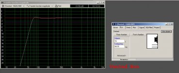
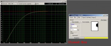
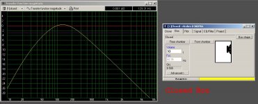
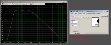
Ok, vented vs closed on the mid.
This is what I get in WinISD.
- Using a vented chamber I have a cut-off frequency of 70 Hz.
- Using a closed chamber I have a cut-off frequency of 150 Hz.
This is what I get in WinISD.
- Using a vented chamber I have a cut-off frequency of 70 Hz.
- Using a closed chamber I have a cut-off frequency of 150 Hz.
Attachments
- Status
- This old topic is closed. If you want to reopen this topic, contact a moderator using the "Report Post" button.
- Home
- Loudspeakers
- Multi-Way
- New 3-way project - "The French Touch"