It most likely has two power rails: a power supply with a positive and negative half that are at the same voltage from ground (ig +30V and -30V). This is often done with two separate windings on the same transformer, but for availability or other reasons they went with two transformers. (perhaps two were cheaper than one special made one)
No, it has not two power rails. The srm monoblock has only one rectiflier.
The transformers are connected in parallel. If this really helps this amp is debatable.
From what I understand they only buy one size of toroidal transformers used in most of there amplifier products.
The transformers are connected in parallel. If this really helps this amp is debatable.
From what I understand they only buy one size of toroidal transformers used in most of there amplifier products.
")
Let's be clear, there are 4 diodes in a bridge rectifier. That doesn't mean it handles any more than one supply of balanced, +/- rails. If there are 2 rail voltages, there need to be 2 bridge rectifiers. That's a total of 8 diodes.
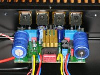
In the R/H pic, the windings from each transformer are paralleled at the PCB connection, so 1 trafo supplies one rail, the second supplies the other.
Anyone like to suggest how else it could be wired with effectively only one winding from each trafo?
In the R/H pic, the windings from each transformer are paralleled at the PCB connection, so 1 trafo supplies one rail, the second supplies the other.
Anyone like to suggest how else it could be wired with effectively only one winding from each trafo?
You can wire a +/- supply with only 2 diodes with the disavantage that the ripple will be 50 Hz and there will be a demand for bigger filtercapacitors.
And making +/- supply with only one bridge rectifier is no problem, you can use 2 bridges, but that only ad noise and power loss to the system.

And making +/- supply with only one bridge rectifier is no problem, you can use 2 bridges, but that only ad noise and power loss to the system.
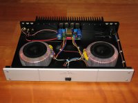
Can anybody tell me what the idea behind this design is?
To balance the weight evenly accross the enclosure, to make it feel more 'hifi' ?
But only 1000uF filter caps ??
Quite so, those are possible rectifier arrangements for dual winding transformers.You can wire a +/- supply with only 2 diodes with the disavantage that the ripple will be 50 Hz and there will be a demand for bigger filtercapacitors......And making +/- supply with only one bridge rectifier is no problem, you can use 2 bridges, but that only ad noise and power
However, neither follow the wiring of the posted image, where there is, effectively, only 1 secondary winding in each trafo, because each pair of leads from each trafo is simply paralleled before rectification.
ergo: It cannot be either A or B circuits.
Last edited:
To me it looks mostly like the B version, but with each of the two secondary windings shown, made up from the pair of windings from of each transformer.
Net result one transformer for the positive one for the negative, each transformer has 2 secondaries wound in phase (parallel).
Thanks
-Antonio
Net result one transformer for the positive one for the negative, each transformer has 2 secondaries wound in phase (parallel).
Thanks
-Antonio
However, neither follow the wiring of the posted image, where there is, effectively, only 1 secondary winding in each trafo, because each pair of leads from each trafo is simply paralleled before rectification. ergo: It cannot be either A or B circuits.
Hi there,
it is schematic 'B' indeed. The fact that it uses two transformers doesn't matter - just take the 'B' scheme and 'cut' the transformer in two between the two secondary windings to make it clear.
Doing a symmetric +/- rail supply using two windings of the same transformer is just the same as using two separate transformers. In the case shown, each transformer seems to have two windings which are paralleled, for what reason ever. Maybe simply because they had the transformers and needed more power.
Apart from the transformer question, the housing looks quite empty and 1000µF of filtering per rail is next to nothing - to me this amp looks somewhat like a lot of show and much less on the inside....
Rundmaus
The two windings of each toroid is paralelled.
Then the two toroids are connected in this way:
Look at example B over here, and the picture of the rectifier.
The Yellow and Grey to the left is connected to the top of the rectifier.
The Blue and Red AND the Yellow and Grey are connected to GND/Center tap for the caps.
The Blue and Red are connected to the bottom of the rectifier.
Certainly very odd. Why such a poorly specced amp would need two huge transformers is indeed a mystery.
1000uF caps in the PSU... ?
Something like a Pass F5 wouldn't have too many components either and may have two transformers but the rest of the space would have at least a couple of respectable reservoir caps.
1000uF caps in the PSU... ?
Something like a Pass F5 wouldn't have too many components either and may have two transformers but the rest of the space would have at least a couple of respectable reservoir caps.
Last edited:
Certainly very odd. Why such a poorly specced amp would need two huge transformers is indeed a mystery.
1000uF caps in the PSU... ?
Something like a Pass F5 wouldn't have too many components either and may have two transformers but the rest of the space would have at least a couple of respectable reservoir caps.
On the amplifier board there is a bit more capacitance, so no problems.
This amp really delivers the current needed to obtain a "stiff" amp, disreggaqrding the load.
The power doubvles from 8 Ohms to 4 Ohms and nearly that to 2 Ohms.
Only possible my having sufficient VA fon the transformers.
And as stated here: Cheaper than a single BIG Toroid, needing a mmuch larger enclosure.
Lots of VA, and a low profile case with standard toroidals.
Cheaper (plus fits in the GM philosophy).
But wouldn't that normally go hand in hand with a few more uF.
I can see where you might need lower profile so you are forced to use a lower VA transformer, but custom made cores are available for that task. I can't believe that a manufacturer would find it cheaper to fit two transformers in such a low spec amp.
- Status
- This old topic is closed. If you want to reopen this topic, contact a moderator using the "Report Post" button.
- Home
- Amplifiers
- Solid State
- 2 toroids in monoblock?