I'm looking to build a simple DIY two channel amp so I can run my computer sound card through a pair of 8Ohm Realistic Minimus 77 speakers.
I'm doing this mostly to learn more about building amps, but also in order to have a better sounding computer speaker than I currently have.
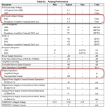
I've attached a datasheet on my computer sound card's output. I've highlighted the two sections I think I'm interested in with a red box. My question to the group, if the output Z of the sound card is 100 ohms what would I want my input Z of my amp to be? Or more specially what rule of thumb, or formula do I use to calculate that? I know I don't want to "load down" the sound card with too low a impedance.
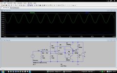
I've also attached a drawing of a circuit I'm considering using for this. Though my other option is a simpler circuit based on the LM386. The part I like about the attached circuit over the LM386 is as I learn more, I can upgrade and tweak the circuit to make it better.
Thoughts?
- Craig
I'm doing this mostly to learn more about building amps, but also in order to have a better sounding computer speaker than I currently have.
I've attached a datasheet on my computer sound card's output. I've highlighted the two sections I think I'm interested in with a red box. My question to the group, if the output Z of the sound card is 100 ohms what would I want my input Z of my amp to be? Or more specially what rule of thumb, or formula do I use to calculate that? I know I don't want to "load down" the sound card with too low a impedance.
I've also attached a drawing of a circuit I'm considering using for this. Though my other option is a simpler circuit based on the LM386. The part I like about the attached circuit over the LM386 is as I learn more, I can upgrade and tweak the circuit to make it better.
Thoughts?
- Craig
Attachments
Get some 10+10 to 15+15W amp kit, using a TDA2030 or TDA2050 or LM1875 chip amp per channel, plus the corresponding power supply.
Nice power, matches your speakers, is easily driven by a PC soundcard and easy/inexpensive to build.
An LM386 is less than 1W, not worth the effort.
Nice power, matches your speakers, is easily driven by a PC soundcard and easy/inexpensive to build.
An LM386 is less than 1W, not worth the effort.
opamp plus transistors can work, but save yourself a lot of hassle and use a symmetric supply rather than a single voltage source.
Soundcards - it varies. To be safe stick with 47K impedance or higher.
For driving speakers you will want something better than 2n5401/2n5551, such as BD139/140 or possibly some TO-220 devices. Better still use some combination to make Sziklai output pairs and you'll get pretty good performance.
This project, designed for headphones but can also easily drive small speakers, may give you some clues: Headphone Amplifier
Hi Craig,
With the component values you have shown, you won"t be loading your
sound card anywhere near its limits.
I once built an amplifier very similar to yours, except that mine was running from dual supplies.The sound quality, to say the least, left a lot to be desired.
The lesson I have learned from that experiment is that non-biased output
transistors MUST be avoided.There are a few steps you can take to make
the amplifier more 'listenable'.
1.Connect the output of the opamp to the base of the upper transistor.
2.Bias the output transistors (A string of diodes, a Vbe multiplier or any other
method of your choice.) Don't forget the emitter resistors after biasing.
3.Connect an R form the base of the lower transistor to the ground.This will
keep the opamp in Class A.Perfectionists may prefer a CCS.
Hopefully, you will have a better amplifier now, albeit a little more component
count than when you started.
Happy soldering
Selim
Do you have a schematic for something like this? Or perhaps can you link one?
Hi Craig,
With the component values you have shown, you won"t be loading your
sound card anywhere near its limits.
I once built an amplifier very similar to yours, except that mine was running from dual supplies.The sound quality, to say the least, left a lot to be desired.
The lesson I have learned from that experiment is that non-biased output
transistors MUST be avoided.There are a few steps you can take to make
the amplifier more 'listenable'.
1.Connect the output of the opamp to the base of the upper transistor.
2.Bias the output transistors (A string of diodes, a Vbe multiplier or any other
method of your choice.) Don't forget the emitter resistors after biasing.
3.Connect an R form the base of the lower transistor to the ground.This will
keep the opamp in Class A.Perfectionists may prefer a CCS.
Hopefully, you will have a better amplifier now, albeit a little more component
count than when you started.
Happy soldering
Selim

Yeah Craig, that's a terrible circuit for audio. It might be appropriate for a DC servo buffer.
Try an LM1875 chip. It's simple and you can build a circuit with a bare minimum of components. You can experiment with tweaking it too without getting too deep. You can use single or dual supply. A google search will yield hundreds of circuits. You might be surprised with the results.
Try an LM1875 chip. It's simple and you can build a circuit with a bare minimum of components. You can experiment with tweaking it too without getting too deep. You can use single or dual supply. A google search will yield hundreds of circuits. You might be surprised with the results.
Hi JMFahey,
Sorry my mistake, its HAL OPB not HALOpB. Anyway here is the link to it.
http://www.diyaudio.com/forums/solid-state/207746-hal-opb-amplifier.html
Thanks,
Sorry my mistake, its HAL OPB not HALOpB. Anyway here is the link to it.
http://www.diyaudio.com/forums/solid-state/207746-hal-opb-amplifier.html
Thanks,
Yeah Craig, that's a terrible circuit for audio. It might be appropriate for a DC servo buffer.
Try an LM1875 chip. It's simple and you can build a circuit with a bare minimum of components. You can experiment with tweaking it too without getting too deep. You can use single or dual supply. A google search will yield hundreds of circuits. You might be surprised with the results.
Thanks for the info. Can anyone assist with understanding the data sheets for some of these amps? Based on the data sheet from my sound card what input sensitivity should the amp have? I see values like 300mv @ 150k ohm, 100mv @ 20k ohm and 75mv @ 20k ohm.
Any tips would be great! Lots of circuits to choose from. I just want to pick the correct one.
Thanks all!
Just build the cicuit suggested in the chip amp datasheet (or buy a kit) and use a volume control in its input, so you set it where you like it best.
Any value from 2x10K to 2x100K will do.
Audio or Logarithmic taper (curve) is best but if unavailable, a Linear curve will do.
Anyway you will adjust it once to some useful level and then control volume from your Soundcard.
Any value from 2x10K to 2x100K will do.
Audio or Logarithmic taper (curve) is best but if unavailable, a Linear curve will do.
Anyway you will adjust it once to some useful level and then control volume from your Soundcard.
- Status
- This old topic is closed. If you want to reopen this topic, contact a moderator using the "Report Post" button.
- Home
- Amplifiers
- Solid State
- Simple DIY Amp