I am trying to get a bipolar voltage to a small AMP. I need 15-0-15 but can go up to 18-0-18. This is the second transformer I bought trying to accomplish this. I wired as per the included schematic for a parallel connection. I only get 10 Volts per leg instead of the 17 listed. I have attached a pic of what I have done and what I need. What am I doing wrong? Did I order the wrong transformer for my needs again?
It is a Hammondmfg model 161G34 ct transformer with the secondaries wired in parallel. The link above is exactly how I wired it.
I am getting 10 volts on each leg coming out which is terminals 3 and 6. I have the 0 volt terminal on my amp board connected to ground and the two 15 volt terminals wired one into 3 and one into 6.
Help please?
An externally hosted image should be here but it was not working when we last tested it.
It is a Hammondmfg model 161G34 ct transformer with the secondaries wired in parallel. The link above is exactly how I wired it.
I am getting 10 volts on each leg coming out which is terminals 3 and 6. I have the 0 volt terminal on my amp board connected to ground and the two 15 volt terminals wired one into 3 and one into 6.
Help please?
above link not working
here is the link to the manufacturer's download page
http://www.hammondmfg.com/pdf/160_161Bulletin.pdf
sorry I can not seem to get an image to load on here argh another help topic hahahaha
here is the link to the manufacturer's download page
http://www.hammondmfg.com/pdf/160_161Bulletin.pdf
sorry I can not seem to get an image to load on here argh another help topic hahahaha
Try UN-paralleling the transformer secondary windings, and not having them connected to anything else at all, and then measure across each one.
The 78xx series input voltages are rated at up to 35V.
Their Dropout Voltage specs are 2V, at 1A output current. But you would want to have more than the bare minimum, so say 5V.
That means input voltages should be about +/- 20V for the 7815 and 7915.
Transformer output voltages are rated in Volts AC, RMS. So the peak output voltage will be sqrt(2) higher than that, i.e. 1.414X higher.
However, sometimes they are rated when no load is attached and other times when full load is attached.
Your transformer has dual 17V 300 mA secondary windings (34V 300 mA when in series and 17V 600 mA when paralleled). If you only have one transformer, I think that you won't parallel (or series) the secondaries, since you will need one secondary for each polarity, unless you have an unusual circuit, but I can't see any schematic or photo. [Use the paperclip icon, after clicking "Go Advanced".] 300 mA is not a lot of current.
Each winding is rated at about 5 VA (about 5 Watts, in RMS terms). You should count on having about half that much as your maximum output power, unless you don't mind using excessive amounts of smoothing capacitance, to keep the ripple in check when near maximum output power, so your regulators won't violate their dropout specs, which gets ugly really fast.
Anyway, 17V AC RMS should have peaks at about 24 Volts. You will connect the AC from the secondary(s) to a bridge rectifier, and the bridge's output will go across smoothing capacitors, and the regulator will also be across the smoothing capacitors. The rectifiers will drop the voltage by one or two volts. So you need to use enough capacitance to only allow about 2V or ripple. The BOTTOMS of the ripple voltage waveform must not be able to dip into the regulator's dropout region, which will be at least 17V if the output is 15V, but a safety margin must also be left, to account for low mains voltage, transformer regulation, et al. See the following link:
Unregulated Power Supply Design
C >= i / (2fΔv)
If you allow for 0.6 Amps, and f = 60 Hz, and Δv is selected to be 2V ripple (peak-to-peak), that gives C >= 0.0025 Farads, or 2500 uF. I would use 4700 uF, or maybe 3300 uF, rated at 25 Volts or higher. (Yeah, I estimated such that those came out on the high side. You could try 2200 uF, but you might end up with problems when near max output power.)
Last edited:
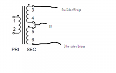
Without seeing the board or the schematic it is a bit hard to tell what you need to do but the attached pic (modified from the hammond one) shows roughly what I would expect to be normal for wiring the transformer from what you have said.
So the centre would go to the 0V point on the board, and the other two leads would go (I assume) to what you called points 3 and points 6. However it would be good to see a board layout and schematic before doing this to make 100% sure!
Tony.
So the centre would go to the 0V point on the board, and the other two leads would go (I assume) to what you called points 3 and points 6. However it would be good to see a board layout and schematic before doing this to make 100% sure!
Tony.
Attachments
I am trying to get a bipolar voltage to a small AMP. I need 15-0-15 but can go up to 18-0-18. This is the second transformer I bought trying to accomplish this. I wired as per the included schematic for a parallel connection. I only get 10 Volts per leg instead of the 17 listed. I have attached a pic of what I have done and what I need. What am I doing wrong? Did I order the wrong transformer for my needs again?
An externally hosted image should be here but it was not working when we last tested it.
It is a Hammondmfg model 161G34 ct transformer with the secondaries wired in parallel. The link above is exactly how I wired it.
I am getting 10 volts on each leg coming out which is terminals 3 and 6. I have the 0 volt terminal on my amp board connected to ground and the two 15 volt terminals wired one into 3 and one into 6.
Help please?
What is "ground" that you connected to?
Is that pins 4 and 5 of the transformer, connected together?
Try measuring right across the transformer pins, not somewhere else in your circuit, at first. From 3 to 4 should be 17V, or more. From 5 to 6 should be 17V, or more. From 3 to 6 should be 34V, or more.
NOTE that if you connected 3 to one place and 6 to another place, and are presumably connecting 4 and 5 together, then your windings are NOT in parallel. And they are not in series. They are being used as separate center-tapped windings, one for each polarity.
Thanks guys here is a link to the board that I am trying to power:
Volume Control Board Component DIY Kit 10 Times Pre Amp | eBay
I have not so far connected it to the circuit. I have been trying to get the voltages correct by simply checking voltages and wiring secondaries on a breadboard. The circuit goes straight from the input terminals to a bridge rectifier and capacitors for the smoothing circuit built into the circuit board. I understand those things fairly well but the transformer wiring is killing me. I have not run anything from the transformer secondaries to a ground. The 0 Volt input on the circuit board is however run straight to ground. I thought all I needed from the transformer to the circuit was the 2 power legs one being +17V and one being -17V. I will read through the sites that you guys have recommended for me to read. I always get good reference sites from here. You guys are the best!
Connect 3 and 5. Connect 4 and 6. Run those two to the two "AC" pads on your board, in any order. (That connection order properly parallels the secondaries.)
Before soldering those, make sure that those two wires (that go to the "AC" pads) are tightly twisted together, all the way to each end, with at least 4 turns per inch.
Also make sure that the ac input wires are twisted the same way. If you have a power switch in one of the ac wires, run both wires to it, twisted all the way, except where one of them goes around the switch.
Otherwise, they will be hum transmitting antennas.
Last edited:
Thanks gootee but that is how I already have everything including the twisted wires. 3 to 5 gives me 10V and 4 to 6 gives me 10V. If I measure 3 to 6 I get 19V. That is why I am so confused. I wired it that way per the directions that came with the transformer. Thinking of trying wintermute's way because that is how the other transformer I tried was wired. It was a 20 Volt CT and gave me solid 10V out each leg. It makes sense to wire a 34 Volt CT that way and get 17V per leg but the manufacturers schematics do not list it.
Hi Bradford336, after wiring the transformer up with four and five together. check that you get 34V between 3 and 6 (you should).
*If* you get zero volts then the secondaries are wired out of phase and you should try 4-6 for the zero volts. then you should get 34V between 3 and 5.
assuming that the first is correct, you run 3 and 6 to your AC in on your board, and the junction between 4 and 5 to the zero volts on your board. Aas your board only has two AC in's and a zero volts I'm reasonably confident that that is how it is configured. If it was running dual bridges it would be wired differently.
Tony.
- Status
- This old topic is closed. If you want to reopen this topic, contact a moderator using the "Report Post" button.
- Home
- Amplifiers
- Power Supplies
- trying to get 15-0-15