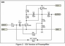
Hi folks, I built the ESP microphone amp for measurement of speaker outputs (schematic attached). However I can't get it to work.
The only difference to the ESP is I had to use NTE transistors as I couldn't find the BC549 at my local store, they are supposed to be the equivalent.
I also didn't have electrolytic caps, so I put poly caps in instead (pic attached).
However it doesn't work, when I put my finger on the mic input I get the typical buzzing sound so the circuit is live and seems to be working, I tried a few different electret mics I had around and get virtually no sound out of them.
Does this circuit only work with electrolytics?
Thanks for the help
Chris
Attachments

What NTE-transistor did you put in?
Electret mics generally need a power supply.
Have You checked that the ones You have is suitable to connect directly to this amp?
There is no power for the electret in this cirquit.
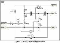
Try putting another capacitor on the input, and then a 27K resistor from the +12V to the output of the mic, wich is to be connected to the new caps other end.
By the way. As You use film caps here, just put the 27K resistor in between +12V and the gain-resistor. The end going to the input of the amp.
Electret mics generally need a power supply.
Have You checked that the ones You have is suitable to connect directly to this amp?
There is no power for the electret in this cirquit.
Try putting another capacitor on the input, and then a 27K resistor from the +12V to the output of the mic, wich is to be connected to the new caps other end.
By the way. As You use film caps here, just put the 27K resistor in between +12V and the gain-resistor. The end going to the input of the amp.
Last edited:
What NTE-transistor did you put in?
Electret mics generally need a power supply.
Have You checked that the ones You have is suitable to connect directly to this amp?
There is no power for the electret in this cirquit.
Try putting another capacitor on the input, and then a 27K resistor from the +12V to the output of the mic, wich is to be connected to the new caps other end.
By the way. As You use film caps here, just put the 27K resistor in between +12V and the gain-resistor. The end going to the input of the amp.
Thanks, I'll give it a try and report back
") Just to confirm it should look like the attached schematic?
Just to confirm it should look like the attached schematic?EDIT: actually this puts DC on the output, I'll add a cap and resistor to Vcc instead
Attachments
Last edited:
- Status
- This old topic is closed. If you want to reopen this topic, contact a moderator using the "Report Post" button.