Hello
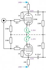
Here is what I tried, it works but sound is unpleasant, dull, flat, no mid-range, no emphasis, etc. Too much treble because of "no mid-range" I guess.
Not so bad on electronic music (lot of bass and not much treble) but there is definitively a problem..
I tried local feedback with 300K resistors between 807 plate and EF80 plate: worse..
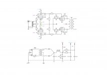
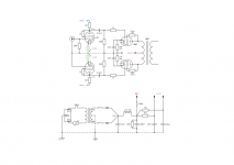
Sowter 8920 input phase splitter transformer.
Just for testing, I added a 1M pot at the output of the preamplifier to introduce a serious roll-off at high frequencies: too colored / mellow but it sounded much better like this!
Do you see something wrong ? thanks.
Here is what I tried, it works but sound is unpleasant, dull, flat, no mid-range, no emphasis, etc. Too much treble because of "no mid-range" I guess.
Not so bad on electronic music (lot of bass and not much treble) but there is definitively a problem..
I tried local feedback with 300K resistors between 807 plate and EF80 plate: worse..
Sowter 8920 input phase splitter transformer.
Just for testing, I added a 1M pot at the output of the preamplifier to introduce a serious roll-off at high frequencies: too colored / mellow but it sounded much better like this!
Do you see something wrong ? thanks.
Attachments
How did you determine the value of the 10k resistor on the secondary of the input trans? Looking at the datasheet is says: A secondary Zobel network consisting of 47k Ohms in series with 150 pF across the two secondary windings in series may be use to adjust the resonance behaviour. This may need to be varied depending on the actual input capacitance of the driven stage.
According to the datasheet, the transformer works with a 20K+20K load.
According to the datasheet, the transformer works with a 20K+20K load.
How did you determine the value of the 10k resistor on the secondary of the input trans?
Frankly I don't know what I am doing

10K load at secondaries was recommended when using this transformer as isolating for my previous preamplifier.
This way (picture) ?
Did you try global feedback?
Not yet.
Attachments
What's the voltage from the supply? Is the power tranny 240-0-240, or 120-0-120?
240-0-240
First double check things are going wrong upstream of your amp's input jack. If you have another amp plug it in and confirm everything sounds right with a working amp in place.
To to get a baseline that your amp works, as long as your input jacks are isolated from the chassis, split phase at the input jack. Just connect one grid to the pin and the other grid to the jack ground. Remember to add a grid resistor, 100K to 220K from each EF80 grid to ground (this can be done at the jack). I would also get rid of the 1K grid stopper, at least for a first listen. If the amp still sounds bad then your issue is not the input trans.
If the amp sounds good with the input trans out, you can try putting it back in, but you may not need to. Try it with unconnected secondaries--each leg connected directly to the grid, then with the 47K cap across the secondaries. You can also parallel the secondaries, dot to dot, and see if that helps. You are running all triodes so I don't think feedback will help with the issue you describe.
Matt
This supply is probably 240-0-240 giving you 300V at the first cap. 300V is a good voltage for a triode connected 807 so should work fine. You could try lowering the cathode resistors to increase current through the 807s. You could try 510 ohm and 470 ohm. Measure the voltage drop across the resistor and use ohm's law to determine the current. Shoot for < 60mA.
Before that, I would listen to the amp with the zobel you have put on the schematic to see how that changes the sound. Or you could put 20k ohm resistors across each secondary of the input transformer to see how that changes the sound.
So, you have several simple things you can try. I think the overall topology of the amp is very good.
Thank you for your help.
This morning I tried with 20K+20K in series across the secondaries, it's better but still "harsh".
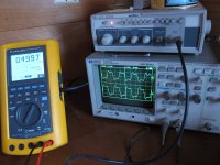
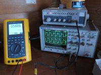
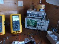
Time to learn how to use a scope and signal generator. I disconnected output stage and connected probes after the coupling capacitor (0.22uF).
Here are some picture and a video. It's awful, right ? what's going on
https://dl.dropbox.com/u/425350/QS2/MVI_1979.MOV
This morning I tried with 20K+20K in series across the secondaries, it's better but still "harsh".
Time to learn how to use a scope and signal generator. I disconnected output stage and connected probes after the coupling capacitor (0.22uF).
Here are some picture and a video. It's awful, right ? what's going on
https://dl.dropbox.com/u/425350/QS2/MVI_1979.MOV
Attachments

I replaced 150 ohms resistors between plate and screen with 1K.
4K3 grid stoppers instead of 1K. Same results.
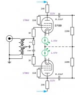
So I disconnected the input transformer and tried like this but phase splitting doesn't work, lower EF80 doesn't split anything. Incorrect ground ?
Input socket is isolated from chassis, the only path to ground is through the lower 150K grid leak resistor I guess.
4K3 grid stoppers instead of 1K. Same results.
So I disconnected the input transformer and tried like this but phase splitting doesn't work, lower EF80 doesn't split anything. Incorrect ground ?
Input socket is isolated from chassis, the only path to ground is through the lower 150K grid leak resistor I guess.
Attachments
I find the lowest value terminating resistor your preamp can still drive to produce the smoothest result. I often go as low as 1K (but I generally go with a step down ratio of at least 4:1+1 so thats not a bad load really).
Try something really low and see how it sounds.
Shoog
Try something really low and see how it sounds.
Shoog
Sorry I mislead you there. Solder one lead of a 100K resistor to the central "+" pin of your input jack, and the other end of the 100K resistor to the ground tag of the same jack. Another wire goes from the central pin to one EF80 grid. The central pin as one leg of the resistor and the grid wire connected.
From the jack's ground tag you need a wire to the circuit ground and directly to the grid of the other EF80. So the ground tag has the other end of the resistor and a wire(s) to the other EF80 grid and to circuit ground. You should get a zero reading from input jack ground tag to circuit ground.
Get rid of the 4K3 grid stoppers for now and go from the input jack directly to the grids. Sorry about the confusion.
I don't understand your dotted line in the drawing, you have zero resistance from the LED ground to the circuit ground correct?
Matt
You're edging toward dangerous territory 6J7... While a well behaved tube won't have voltage on the grid to speak of (especially with the 150K to ground connections), I'm nervous about not having a DC blocking cap. But ... let's keep moving, ... no cap.
OK - you're right - the bottom half is doing nothing. It should not be hooked up to the jack at all, actually, just ground. And the outer-ring of the jack SHOULD definitely be attached to ground, not the grid of the pentode in the lower half. That may be part of your signal-generator-and-oscilloscope problem.
ONTO oscilloscopes. Remember to attach the ground-alligator-clamp (of the probe) to ground. If you don't , you'll get all sorts of waveforms that look ... unsurprisingly ... like the ones you captured.
Does your signal generator have a triangle wave output? Its actually better for debugging things than the square wave.
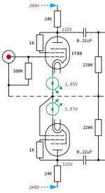
FINALLY - I'm against counting on the "right bias" coming from the pair of LED diodes that are cathode connected. The variance of tubes is so great that it is entirely likely that the bias-point is way off. This alone could count for quite a bit of non-linearity in the runtime behavior of the circuit. The design ... is nice ... but please do try to substitute an appropriate resistor and simple cheap electrolytic bypass capacitor, yes? If you're expecting a bias-point of +1.97 volts (say), and 5.25 milliamps (which I found by dividing the voltage-difference between plate supply and plate voltage, by 24K)... then working backward from E=IR... R=E/I ... = 2v / 5.25ma = 380 ohms. You might want to make it adjustable (500 ohm adjustment pot), so that you can SET the plate-voltage points of each tube to be very close to each other.
After that, just test each section (upper, lower half) in turn, by connecting the grid to the jack pin, as you have shown in the above diagram. You'll likely find now that with all the above advice taken, that the output waveforms are much cleaner. Having done that, it can be reconfigured per your original design ... less the LED voltage-drops, and with the RC bias convention in place.
GoatGuy
OK - you're right - the bottom half is doing nothing. It should not be hooked up to the jack at all, actually, just ground. And the outer-ring of the jack SHOULD definitely be attached to ground, not the grid of the pentode in the lower half. That may be part of your signal-generator-and-oscilloscope problem.
ONTO oscilloscopes. Remember to attach the ground-alligator-clamp (of the probe) to ground. If you don't , you'll get all sorts of waveforms that look ... unsurprisingly ... like the ones you captured.
Does your signal generator have a triangle wave output? Its actually better for debugging things than the square wave.
FINALLY - I'm against counting on the "right bias" coming from the pair of LED diodes that are cathode connected. The variance of tubes is so great that it is entirely likely that the bias-point is way off. This alone could count for quite a bit of non-linearity in the runtime behavior of the circuit. The design ... is nice ... but please do try to substitute an appropriate resistor and simple cheap electrolytic bypass capacitor, yes? If you're expecting a bias-point of +1.97 volts (say), and 5.25 milliamps (which I found by dividing the voltage-difference between plate supply and plate voltage, by 24K)... then working backward from E=IR... R=E/I ... = 2v / 5.25ma = 380 ohms. You might want to make it adjustable (500 ohm adjustment pot), so that you can SET the plate-voltage points of each tube to be very close to each other.
After that, just test each section (upper, lower half) in turn, by connecting the grid to the jack pin, as you have shown in the above diagram. You'll likely find now that with all the above advice taken, that the output waveforms are much cleaner. Having done that, it can be reconfigured per your original design ... less the LED voltage-drops, and with the RC bias convention in place.
GoatGuy
If I was you I would make the Tabor clone design of Shoog.
Proved concept, good reports, trusted designer(s)
Listening to that amp right this second. After a few teething troubles initially, it has become my standard amp for the bedroom. I had similar issues with the input transformer until I loaded it down with a 1K resistor. I believe the toroidal power transformer I utilized for the input has a step down ration of 9:1+1 (to much gain with 1:1+1) and tends to to ring out at 60khz. The only CCS I could get which were capable of coping with the switch on transients were the IXY 900V chips, since then I tend to use 125V versions of the LM317 protected with zeners.
Currently building a new version using EL86's with a few interesting twists. Has a few issues so far but will be testing again at the weekend.
All the credit must go to Gary Pimm who designed the original (and best) Tabor.
Shoog
Last edited:
I don't understand your dotted line in the drawing
The dotted line is the circuit ground.
you have zero resistance from the LED ground to the circuit ground correct?
That's right.
I'll try first with the led's (as you can see on the schematic, EF80 plates voltage are the same, anyway I have no clue about transconductance, maybe the most important in this case ?). Then with unbypassed cathode resistors, then bypassed for more gain.
Pictures tomorrow when done, squares + triangles.
Thank you all for your help, very appreciated
Attachments
Just out of interest - because of the design of the 807, which was optimised for low screen current, it is not generally very efficient running them as triodes. i think they are only rated at 1-2Watts per tube in triode mode. The same tubes can give 10watts class A in pentode mode.
They are also prone to generating high order harmonics, which makes some form of feedback mandatory to get a clean presentation.
Shoog
They are also prone to generating high order harmonics, which makes some form of feedback mandatory to get a clean presentation.
Shoog
As many have noted, there is nothing wrong with your schematic, the amp should sound good. If you are still hearing problems try taking a photo of the wiring because someone may catch something you have over looked.
Enjoy the music for a while first if you get it sorted. Wait a bit until you start screwing with it, though that is a different kind of fun entirely and addictive.
There will be lots of suggestions of things you can try. Put the input trans back in and play around with no loading between secondary legs, resistor loading and network loading. Force AC balance of your driver cathodes by putting the drive cathodes over a constant current source or a choke or even a resistor w/o bypass cap. You might find a negative supply for the cathode “ground” helps keep driver tube plate current where it needs to be.
Increasing plate current in driver and outputs might change things to your liking, or not. Then once you have the signal circuit sorted you can start screwing with the power supply which can have surprisingly more impact on sound than you would think---even for Push Pull which is supposedly “immune” to power supply changes.
Matt
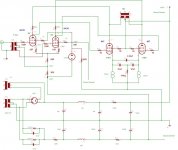
Upper EF80 works, and as I can see on the scope, there is a big improvement.. but I can't listen how it sounds because lower EF80 still doesn't split anything ! tube seems to be good, led on, plate voltage ok. But no signal at all, tried to change the probe, same result.
Here is what I did.
Here is what I did.
Attachments
- Status
- This old topic is closed. If you want to reopen this topic, contact a moderator using the "Report Post" button.
- Home
- Amplifiers
- Tubes / Valves
- 807pp + input phase splitter