Hi,
I'm building some DIY speaker cables and have been reading about resistance, capacitance and inductance; R and L being more significant than C.
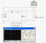
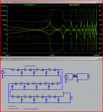
I have used Electronics Work Bench to approximate a cable model (click attached thumbnail for image) and was hoping to get some comments about how valid or useful this approach is.
It seems to confirm much of what is said about capacitance affecting high frequency performance less than inductance and resistance i.e. when I change C not much happens but when I chance R and/or L the upper cut-off point can encroach on the audio band.
Note: The speaker impedance (Z) is a crude constant in this model as I'm not sure how to model the reactance of a typical speaker without actually drawing it in complete and given speakers vary quite a bit, maybe there is little point. Also, It's easy to increment Z and re-run the simulation to see the effect of changes in speaker impedance.
Any comments much appreciated.
HNY,
Dean.
I'm building some DIY speaker cables and have been reading about resistance, capacitance and inductance; R and L being more significant than C.
I have used Electronics Work Bench to approximate a cable model (click attached thumbnail for image) and was hoping to get some comments about how valid or useful this approach is.
It seems to confirm much of what is said about capacitance affecting high frequency performance less than inductance and resistance i.e. when I change C not much happens but when I chance R and/or L the upper cut-off point can encroach on the audio band.
Note: The speaker impedance (Z) is a crude constant in this model as I'm not sure how to model the reactance of a typical speaker without actually drawing it in complete and given speakers vary quite a bit, maybe there is little point. Also, It's easy to increment Z and re-run the simulation to see the effect of changes in speaker impedance.
Any comments much appreciated.
HNY,
Dean.
Attachments
Last edited:
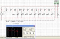
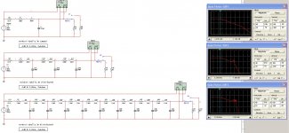
Try a distributed L & C like in real speaker cables.
Lots of little L's and C's...0.8uH / foot and 30pF / foot
Say about 10 feet worth.
It would be interesting to see the results.
Same -1dB point, different response. No real impact on audio band it seems.
Attachments
Last edited:
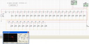
Say about 10 feet worth.
For a 3m cable the -1dB point close to top of audio band!
Attachments
Instead of using a benign Sinusoid for the generator, try a Pulse/ Square wave and see what arrives at load end.
I used the function generator instrument. No real change from sine, square, triangle waves and for different voltages (1v to 10v) apart from the Inductors blew! EWB puts on a nice little animation to that effect.
I'll model some real world cables such as Goertz foils, Pear Anjou, Nordosts, DNM, Naim, Slinky Links to see how they perform for Z=4ohms (just to make it difficult).
I'll model some real world cables such as Goertz foils, Pear Anjou, Nordosts, DNM, Naim, Slinky Links to see how they perform for Z=4ohms (just to make it difficult).
In conclusion: Don't but Nordost!
a couple of posts with LTspice lumped cable model sims, with .asc source for the parameterized lumped TL model
http://www.diyaudio.com/forums/anal...ch-preamplifier-part-ii-3052.html#post3264506
http://www.diyaudio.com/forums/anal...ch-preamplifier-part-ii-3074.html#post3269070
http://www.diyaudio.com/forums/anal...ch-preamplifier-part-ii-3052.html#post3264506
http://www.diyaudio.com/forums/anal...ch-preamplifier-part-ii-3074.html#post3269070
Attachments
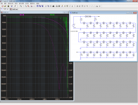
Lumped cable models are essentially useless: for example, here is the comparison between a real, distributed model of a 320m cut and its lumped equivalent (when measured with a network analyzer, the resulting curve is identical to the simulated one [distributed, of course]).
This example is for a 100 ohm cable, but results are applicable to any type.
This example is for a 100 ohm cable, but results are applicable to any type.
Attachments
Lumped cable models are essentially useless: for example, here is the comparison between a real, distributed model of a 320m cut and its lumped equivalent (when measured with a network analyzer, the resulting curve is identical to the simulated one [distributed, of course]).
This example is for a 100 ohm cable, but results are applicable to any type.
cheer Elvee. Just to be sure: green is the lumped sim and purple is both the distributed sim and measured?
I'm getting similar differences between lumped and distributed in terms of shape of curve but the -1dB point came out the same. Maybe a simulation of a longer cable with more distributed "elements" will show differences in line with your graph.
All very interesting.
1uH per section (post 4) is rather unrealistic!
A lumped approximation only works when the frequency is sufficiently low. 320m done in 32 lumps means 10m per lump. The lump needs to be signficantly shorter than a quarter-wave, say 5% of a wavelength. For 10m this means less than 1.5MHz.
The lumped model is fine for audio in domestic audio cables, whether interconnects or speaker cables. It won't tell you about RF ingress, as for that you have to treat the cable as a leaky RF transmission line.
Don't forget to include the amplifier output impedance, which may be greater than the cable impedance and also frequency dependent.
1uH per section (post 4) is rather unrealistic!
That was just a quick distributed version of the first lumped sim just to check for any differences. For say a 3m cable, how should I proceed? Lumped as you mentioned?
Don't forget to include the amplifier output impedance, which may be greater than the cable impedance and also frequency dependent.
That was going to be my next consideration. I'm not sure if EWB includes o/p Z for it's generator components. I've looked at the properties of the generator and can't see anything so I guess I have to include it. From what I've already learned from playing around with the cable resistance, it will make a huge difference.
Lumped is fine for 3m of audio cable.
Generator output impedance can be modelled by adding extra components to the circuit in series with the generator. As a minimum include a resistance calculated from the claimed damping factor. For most solid-state amps this needs an inductor in series to model the effect of the dominant pole loop stabilisation. Then add the output Zobel network.
You will then find that the variations in speaker impedance dominate anyway. Look at published impedance curves for speakers. Assume each peak is a damped resonator (parallel R C L) at first, although more accurate models may be available.
o/p Z...it will make a huge difference.
Just realised, o/p Z is usually pretty low.

Lumped is fine for 3m of audio cable.
Generator output impedance can be modelled by adding extra components to the circuit in series with the generator. As a minimum include a resistance calculated from the claimed damping factor. For most solid-state amps this needs an inductor in series to model the effect of the dominant pole loop stabilisation. Then add the output Zobel network.
You will then find that the variations in speaker impedance dominate anyway. Look at published impedance curves for speakers. Assume each peak is a damped resonator (parallel R C L) at first, although more accurate models may be available.
Cheers DF96. Good suggestions. I have included a small resistor for the o/p Z so far. I'll try to make improvements on that. As for the speaker end: I've been changing the speaker value to see the affect on the -1dB point, not sure if this is that valid but it gives seems to give ball-park, predictable results.
you could clik on my http://www.diyaudio.com/forums/parts/226855-modelling-audio-cables.html#post3307569 links - clearly shows transmission line reflection impedance swings, audio frequency roll-off from resistance in a simulation with lumped parameters, includes resistance, link to Pass' cable article...
Attachments
Hi,
Not read all the other posts, but you will need to add the same lumped elements in the 0volts line - so you have a symmetrical balanced line as the cable proceeds along the x axis.
The values will depend on how they are specified - usually i would expect the capacitance per metre to be across the pair, but the inductance and resistance can be halved per top and bottom section such that they add up to the henries per metre and ohms per metre quoted.
The 0volts is only connected at the output of the unbalanced amplifier - the negative terminal is usually conect to 0volts or ground.
Regards,
Shadders.
Last edited:
gnd return R,L modeling doesn't change conclusions, the "one sided model" is the universal way the lumped approximation is shown in the literature
I think that as a series circuit you will have a hard time finding practical difference from modeling both wire's R,L
for a real cable model accuracy improvement, in my linked post I mention that skin/proximity effect could be modeled with added mutual L, steering high frequency current to some parallel R branches, "concentrating" the current, increasing apparent resistance as the other R paths are starved
Last edited:
- Status
- This old topic is closed. If you want to reopen this topic, contact a moderator using the "Report Post" button.
- Home
- Design & Build
- Parts
- Modelling Audio Cables