Hello!
I can't seem to hook up an opamp without horrible distortion.
I designed some circuits based off many great posts on this site and using a quad opamp but everything I do turns into distortion. It sounds like the amp is being overdriven. I'm testing the circuit using audio from an iPod and putting the output into some headphones.
I finally pulled the opamp onto a separate board and put it into a simple unity gain configuration and I still get overdriven sounding distortion. What could I be doing wrong with a unity gain circuit to cause this?
I've tried this with a cheap opamp from rat shack, and an opa4134 with multiple power supplies.
Any suggestions?
Thanks!
I've never done line level before so I didn't even think that it couldn't drive a pair of headphones. When it's complete, though, hooking it directly to an amp from the output will work?
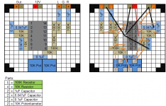
I'm not great at drawing schematics, but I've attached my planned final circuit. It's the same board, left is top down and the right side is from the bottom.
Moving counterclockwise, it's a summing amplifier, an inverting amplifier, and 2 Sallen Key filters. The first is variable frequency and the second is static.
Does this look reasonable? The two single pots will be replaced with a dual gang linear pot when all is done.
I've never done line level before so I didn't even think that it couldn't drive a pair of headphones. When it's complete, though, hooking it directly to an amp from the output will work?
I'm not great at drawing schematics, but I've attached my planned final circuit. It's the same board, left is top down and the right side is from the bottom.
Moving counterclockwise, it's a summing amplifier, an inverting amplifier, and 2 Sallen Key filters. The first is variable frequency and the second is static.
Does this look reasonable? The two single pots will be replaced with a dual gang linear pot when all is done.
Attachments
")
That's not easy to follow tbh. Much better to see it in proper schematic form if you can. It doesn't have to be neat, just drawn on paper is fine.
I see you are running on a single supply so that means the design has to be AC coupled and that you need some means of biasing the opamps to half of the supply voltage for it to work. I can't tell if you have that or not tbh by looking at that. The output pin of each opamp should be at 6 volts on a 12 volt supply. If any isn't you have a problem. So that's something to check.
haha, no, it wasn't meant to follow, it was meant to help build it...
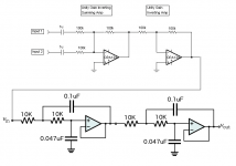
I attached the schematic. I left the pots out. They are wired as variable resistors, so assume they are at 0ohm
I know I didn't take into consideration any biasing of the opamps. If I changed to 4 individual opamps on a common power supply, would this still need any consideration? I'm trying to keep this as simple as possible.
Side question:
Are there any kits or premade products that would do this?
Attachments
If the op amp has no -V voltage, it cannot reproduce the negative portion of the output. So in your inverting circuit, the positive half of the input signal is being chopped off.
An op amp cannot create an output more negative on the low side, or more positive on the high side, than the supply voltage.
Here's a basic tutorial.
Here's a bit more advanced TI application note on single-supply op amp design.
I should add that you can make a split supply from your 12V by using a voltage divider of 2 equal value resistors. By making the junction of the 2 resistors the reference ground point, one end of the divider will be +6V and the other end will be -6V. This and other methods to achieve the same should be easy to find.
Last edited:
This is the simple way to get you started. The two resistors must be equal in value and around 10K. They connect across the supply and junction becomes half supply. The cap is any small electrolytic of around 47 to 100uf. That will bias the opamps to around 6 volts.
Tho output MUST have a cap to AC couple it and for headphone testing add a resistor as mentioned.
Tho output MUST have a cap to AC couple it and for headphone testing add a resistor as mentioned.
Attachments
Thanks so much for the help! I made a quick spit supply and threw a 220k resistor on the output of a unity gain circuit and it works!
I'm a bit busy for the next few days but hopefully I can update my full circuit to run on a split suppll and get that up and running soon. Assuming I wire the split supply correctly, does the existing circuit look good?
I'm a bit busy for the next few days but hopefully I can update my full circuit to run on a split suppll and get that up and running soon. Assuming I wire the split supply correctly, does the existing circuit look good?
Your circuit looks OK electrically.
When you say you "made a split supply", was that a real dual split supply or a virtual split supply (as in my drawing) ? A real split supply could be made from two 9 volt batteries.
Not sure what where the 220K resistor you mentioned fits in (thats really high for a series resistor and it wouldn't drive headphones).
Yeah.... I'm not sure why I put a K there... it's only 220 ohms... =)
The split supply I made was just a voltage divider. My final circuit will have a cap like your drawing. I've seen a few schematics where there's a cap for the 12V and the 6V, but it seems to me that the 12V side wouldn't need a cap at all. I guess it's just to make it look symmetrical?
Question on your drawing, though. It looks like the first half of the circuit is grounded to the virtual ground (6V), and the second half is grounded to the real ground (0V). Am I reading that right?
Question on your drawing, though. It looks like the first half of the circuit is grounded to the virtual ground (6V), and the second half is grounded to the real ground (0V). Am I reading that right?
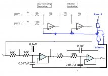
I drew it that because of you using headphones as a load thinking you would take the headphone output ground to the power supply zero. Both the power supply zero and the virtual ground are the same point electrically at AC but the "high" load of the headphones could modulate the virtual ground. That was the thinking
To be absolutely correct all the signal grounds should go to the virtual ground and that becomes the main ground in the system. The power supply zero volts line would go to the opamps and nothing else other than the virtual ground components.
Yes, the virtual ground becomes "proper" ground for the circuit. Its very hard to explain all this in a few words.
The virtual ground... if we take that as our ground and reference point then by definition it is fixed. For it to vary we have to say it varies with respect to something else. That something else are the power rails, the power supply zero point and the 12 volt point. That is the "problem".
As a line stage you have no worries with the simply virtual ground. Just make sure that the caps (we should really use two equal value caps, one across each resistor rather than the economy of a single cap) are large enough like the 47 to 100uf I mentioned.
Well, all was great when hooking it up to headphones. I'm now trying to hook it up to a small class D amplifier, but when I do the circuit stops working. All I get out the speakers is a quiet hum. When I disconnect the amplifier and hook the headphones back up, everything works perfectly (only bass coming through). I know the amp works fine because I can hook normal sources and everything plays well.
The amp and preamp run on the same 12VDC power supply. Could the amplifier be grounding the virtual ground to the power supply ground and therefor pulling the virtual ground to 0? Do I need to ground the amplifier's circuit board to the virtual ground?
The amp and preamp run on the same 12VDC power supply. Could the amplifier be grounding the virtual ground to the power supply ground and therefor pulling the virtual ground to 0? Do I need to ground the amplifier's circuit board to the virtual ground?
Using the circuit in post #11, if your using the same supply for both amps then you need to use the black zero volt line as ground and this connects to the input ground of the Class D amp. The audio input and output grounds now connect to this black line instead of the blue virtual ground.
- Status
- This old topic is closed. If you want to reopen this topic, contact a moderator using the "Report Post" button.
- Home
- Source & Line
- Analog Line Level
- Can't seem to get OpAmps to work