I am a member of diyaudio for a few years now. This is my first post: Thanks a lot for this great forum. It is a joy to know such things exist.
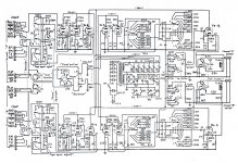
My problem here - I had played around a little with a breadboarded test build of a Marantz 7 phono. It sounded great (even compared to a diy Xono). I decided to put it in box with all the bling and blong needed to be a reliably working pre. The power supply is a tube rectified CLC going into 2 mosfet gyrators for 2 high voltages: 245V and 280V. The original circuit has changed a little bit: There is no cap from grid to cathode of the first gain stage. The feedback cap from the second stage to cathode first stage is only 10 pF. The RIAA network is a little different (I worked it out with B2Spice). The output stage runs a little hotter with 22k/560 Ohm resistors.
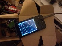
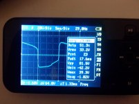
After I had finished I stumbled upon a strange thing. The voltages at the output stage cathode where not as supposed to be: ca 22 volts instead of about 50. With the feedback-loop disconnected everything was fine. There is a picture of a scope trace (measured before the output cap9) with the feedback engaged.
I tried several things. other output caps (new vs old, different values), gridstoppers at the cathode followers grid, bypassing the mosfet-gyrator for the first 2 gain stages, receiving voltage from the output stage gyrator… what else? loading the output stage with other resistances, changing the series resistance values at the output. But no luck. Nothing works. Nothing found in the forums or on the web. I need help. Do you have any suggestions, please???
My problem here - I had played around a little with a breadboarded test build of a Marantz 7 phono. It sounded great (even compared to a diy Xono). I decided to put it in box with all the bling and blong needed to be a reliably working pre. The power supply is a tube rectified CLC going into 2 mosfet gyrators for 2 high voltages: 245V and 280V. The original circuit has changed a little bit: There is no cap from grid to cathode of the first gain stage. The feedback cap from the second stage to cathode first stage is only 10 pF. The RIAA network is a little different (I worked it out with B2Spice). The output stage runs a little hotter with 22k/560 Ohm resistors.
After I had finished I stumbled upon a strange thing. The voltages at the output stage cathode where not as supposed to be: ca 22 volts instead of about 50. With the feedback-loop disconnected everything was fine. There is a picture of a scope trace (measured before the output cap9) with the feedback engaged.
I tried several things. other output caps (new vs old, different values), gridstoppers at the cathode followers grid, bypassing the mosfet-gyrator for the first 2 gain stages, receiving voltage from the output stage gyrator… what else? loading the output stage with other resistances, changing the series resistance values at the output. But no luck. Nothing works. Nothing found in the forums or on the web. I need help. Do you have any suggestions, please???
Attachments
") but isn't the frequency of oscillation a clue here. Could it be due to phase shift caused by the electrolytics adding up at LF ?
but isn't the frequency of oscillation a clue here. Could it be due to phase shift caused by the electrolytics adding up at LF ?And the 0.1uf maybe ?
What happens if you AC couple the feedback take off and move it to the anode of the second valve. That would eliminate the cathode follower and any phase shift in that stage. Would the second valve drive the network, I'm thinking it would for testing.
Try a bigger cap for the 0.1uf though
What happens if you AC couple the feedback take off and move it to the anode of the second valve. That would eliminate the cathode follower and any phase shift in that stage. Would the second valve drive the network, I'm thinking it would for testing.
Try a bigger cap for the 0.1uf though
Merten, a few questions:
1. Are the traces you show happening with no signal in?
2. I can't make out the voltage and frequency of the distorted wave you're showing. What are they?
3. Is the output of the blinged-up power supply stable?
4. Why the really small (0u01) coupling cap from the first stage to the second?
5. What are the tube types for each stage?
Similar to the Marantz 7 phono which used 12AX7A.
Note that the feedback loop is designed to be driven by the moderately low source impedance of the cathode follower so moving it to the plate of the preceding stage is a non-starter.
What mosfet gyrator are you referring to? Are you sure that the source impedance driving the first two stages is low enough to preclude feedback through the power supply at low frequencies?
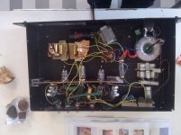
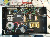
Unfortunately I also suspect the build quality here is playing a big role, I see a lot of very long wires running all over the place, poor layout, etc.
Looks like 50Hz hum pick up??
I would strongly recommend you purchase a copy of Morgan Jone's "Building Valve Amplifiers" 1st edition (2nd due out any century now - I wouldn't wait) as this will help with the required construction techniques.
Note that the feedback loop is designed to be driven by the moderately low source impedance of the cathode follower so moving it to the plate of the preceding stage is a non-starter.
What mosfet gyrator are you referring to? Are you sure that the source impedance driving the first two stages is low enough to preclude feedback through the power supply at low frequencies?
Unfortunately I also suspect the build quality here is playing a big role, I see a lot of very long wires running all over the place, poor layout, etc.
Looks like 50Hz hum pick up??
I would strongly recommend you purchase a copy of Morgan Jone's "Building Valve Amplifiers" 1st edition (2nd due out any century now - I wouldn't wait) as this will help with the required construction techniques.
Man, I am amazed by how fastly and helpfully you all reply. Once again thank you very much.
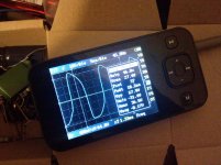
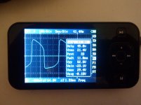
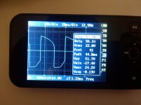
I did some measurements again: one channel now at 12 Hz the other at 45 Hz. With the input shorted there is a small increase (0.2 Hz) in frequency and (0.3 Volts) in Voltage. On the other channel I get an increase of 10 Hz and about 2 Volts if I short the input. Shorted outputs yield the right and stable voltages on one channel, no change on the other. With a load of 33k on the output the oscillating voltage goes down about 5 Volts on one channel, about 10 Volts on the other.
Something very strange, at least to me: the voltage at the cathode is lower ( 33V) than the voltage at the junction between the cathode- and load-resistor (50 V). This on one channel only - the one with higher frequency of oscillation. On the other these voltages are about the same.
And oanother change again: the above voltage were measured with one channel having a coupling capacitance of 0,02uf between the first stages. with 0,01uf like the original circuit the frequency goes up to 29 Hz. (33V)
The strange thing is, one can listen to this monster. no hum (some hum, but tolerable, even with headphones).
Jan, the output voltages are all stable. No hum, no fluctuation. The tubes are all 12AX7 (thanks Kevin). the coupling caps are sized like in the original Marantz 7, as I thought they would affect the equalization. Voltage is about 27V and frequency ca 45 Hz.
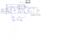
Kevin, the gyrator is a voltage divider at the gate (in series with 220 Ohms) of a IRF820 bypassed with a 22uf cap, with another 22 uF cap at its source for the output; high tension from CLC at the drain. I removed the supply from the gyrator of the first stag (245V) and took the voltage from the other one (280V) decoupling it with 22kOhm and a capacitor, but no change.
Jan, I cant see why it would be PFB?
I am already much more hopefull that I can get this sucker running one day. (I will work on the layout, Kevin).

I did some measurements again: one channel now at 12 Hz the other at 45 Hz. With the input shorted there is a small increase (0.2 Hz) in frequency and (0.3 Volts) in Voltage. On the other channel I get an increase of 10 Hz and about 2 Volts if I short the input. Shorted outputs yield the right and stable voltages on one channel, no change on the other. With a load of 33k on the output the oscillating voltage goes down about 5 Volts on one channel, about 10 Volts on the other.
Something very strange, at least to me: the voltage at the cathode is lower ( 33V) than the voltage at the junction between the cathode- and load-resistor (50 V). This on one channel only - the one with higher frequency of oscillation. On the other these voltages are about the same.
And oanother change again: the above voltage were measured with one channel having a coupling capacitance of 0,02uf between the first stages. with 0,01uf like the original circuit the frequency goes up to 29 Hz. (33V)
The strange thing is, one can listen to this monster. no hum (some hum, but tolerable, even with headphones).
Jan, the output voltages are all stable. No hum, no fluctuation. The tubes are all 12AX7 (thanks Kevin). the coupling caps are sized like in the original Marantz 7, as I thought they would affect the equalization. Voltage is about 27V and frequency ca 45 Hz.
Kevin, the gyrator is a voltage divider at the gate (in series with 220 Ohms) of a IRF820 bypassed with a 22uf cap, with another 22 uF cap at its source for the output; high tension from CLC at the drain. I removed the supply from the gyrator of the first stag (245V) and took the voltage from the other one (280V) decoupling it with 22kOhm and a capacitor, but no change.
Jan, I cant see why it would be PFB?
I am already much more hopefull that I can get this sucker running one day. (I will work on the layout, Kevin).
Attachments
Unfortunately I also suspect the build quality here is playing a big role, I see a lot of very long wires running all over the place, poor layout, etc.
...
Good point. I wonder about the copper foil as well. Another thing to be cautious of is the polystyrene multiple-paralleled-caps: that looks like a lot of soldering, and polystyrene is not very heat tolerant (worse than polyester or polycarbonate, much worse than polypropylene).
I would strongly recommend you purchase a copy of Morgan Jone's "Building Valve Amplifiers" 1st edition (2nd due out any century now - I wouldn't wait) as this will help with the required construction techniques.
Figure another year minimum for BVA2, would be my guess. Two years would not surprise me. BVA is just what Merten needs.
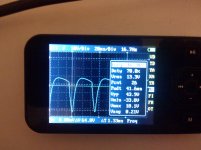
I checked the power supply without the feedback network. There is "no" hum at the output of the gyrators, at least the little pocket scope doesnt show it. There is hum of 0,59 mV at the plate of the first stage. Then at the output tubes cathode there is "something" going on. The scope doesnt give a definitive result. Something around 100 Hz in the region of 100 mV. Picture maybe tomorrow.
It works! I put a 1k resistor into the RIAA network like in the original circuit and raised the feedback cap from 2nd stage to first from 10 pF to 20 pF (also like in M7). Chris from preservationsound suggested this. It sounds great, nice flow.
I have to make everything ordentlich now. And put back the cover.
Thank you all again for your suggestions.
I have to make everything ordentlich now. And put back the cover.
Thank you all again for your suggestions.
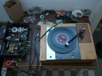
Thanks for the kind words! I am happy too. I have been listening to this now for a while (I have a Lenco L75 on heavy wood plint with Rega RB251 with modified counterweight and a Denon DL103 through beyerdynamic SUTs). I am still surprised by how good it sounds. I have built and listened to JE Labs 6SL7 phono, EAR 834p (with adjustable air caps), some from Sound Practices, the jfet Pacific, opamp-based units (VSPS and phonoclone (Peter Daniels version with op27 and lesser parts)), Pearl 1 + 2 and ONO/XONO and others. With more or less care, so my judgement is very - mmh - so so. Anyway I like this Marantz clone very much, as is said before: timing, tone -very good, a very nice flow. I want to finish my ONO one day though, I thinks its better overall. but I am in no hurry. Maybe I am surprised, because I knew this circuit "all the time", since I learned about electronics. But it had NFB and 12AX7 and cathode followers - it seemed very ugly!
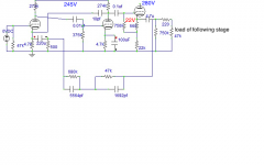
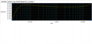
OK. So, the schematics i attached works for me. (The power supply is different.) It started working after I changed the values for the RIAA network to something closer to the ones shown in the schem. There was hum though, exactly what Kevin suspected: coupling through the input tube next to the rectifier tube. Tube moved, copper screens for the input tubes - thicker wire in some places, twisting, shorting some wires, (don't mind the loose socket, please)... its quiet now, tubes hiss only. I had the nerve to try if I could go back to tho old RIAA values. It oscillated again. But not a pity, the graph looks good and it sounds correct. - I love vinyl!
OK. So, the schematics i attached works for me. (The power supply is different.) It started working after I changed the values for the RIAA network to something closer to the ones shown in the schem. There was hum though, exactly what Kevin suspected: coupling through the input tube next to the rectifier tube. Tube moved, copper screens for the input tubes - thicker wire in some places, twisting, shorting some wires, (don't mind the loose socket, please)... its quiet now, tubes hiss only. I had the nerve to try if I could go back to tho old RIAA values. It oscillated again. But not a pity, the graph looks good and it sounds correct. - I love vinyl!
Attachments
- Status
- This old topic is closed. If you want to reopen this topic, contact a moderator using the "Report Post" button.
- Home
- Source & Line
- Analogue Source
- Marantz 7 phono help needed