I am a novice but have had an interest for many years. I have been an Automotive diagnostic technician for my entire life and have done well. I have recently made a decision to pursue electronics blindly and am encountering difficulty breaking problems down in to their respective categories.
I currently have a powered subwoofer in front of me. The transformer was shot. I managed to find the fuse leads in series with the primaries. Fuse is inaccessable so I soldered fuse externally in series with primaries. I tested transformer with ohm meter, then with a light bulb limiter and finally i plugged in to receptacle and tested with voltmeter.
I know now that transformer is good but believe there to be a short circuit on the PCB. At a glance, It has a rectifier, voltage regulators and output transistors along with the many resistors, diodes and capacitors.
Instead of always coming back to ask dumb questions fishing for repair tips, I would like to learn to test and repair myself the correct way.
Please help.
Last edited:
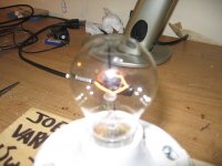
A variac is a type of continuously variable auto-transformer used to bring up the supply voltage gradually. What I believe you meant was you are using a bulb limiter, as pictured.
The bulb limiter is a good way to check for and limit large current draws and to protect circuitry from damage. It is especially useful for powering up either new construction or a repaired item for the first time.
I'll assume you are at least fleetingly familiar with a DMM for automotive electrical diagnostics. You will need to get familiar with basic go / no-go testing of individual electronic components.
I suggest starting with the higher power items that are capable of drawing the kind of current that would have opened the transformers internal fuse. Ensure that there are no shorted diodes in the bridge and check for shorted output transistors first and work inwards from there. Often if an output device(s) have failed there will be collateral damage to driver devices and even further back towards the input is possible. Check to see if a significant DC offset is present at the speaker output, I'd suggest more than 100mV is a potential indicator of issues and >1V is very bad.
Doing your best to secure a copy of the schematic is a huge benefit if you can find it, otherwise you will likely need a little more knowledge and experience to effectively troubleshoot and repair it.
What was the wattage of the bulb? A lower wattage bulb places a lower limit on current flow and will light more brightly than a higher wattage bulb for the same current drawn. Was there any signal or load present? A signal or load may cause higher current draw than the quiescent state we want for testing. For typical class B the bulb will usually glow at least some with no signal or load but shouldn't glow too brightly. A brightly lit bulb is an indicator of something passing too much current.
The light bulb is a 15 watt. I tried another transfor for lack of schematics and known voltage. It blew a fuse as well. It is possible that I under rated the fuse.
I have a 4 amp in there now. Original fuse was 2 amp. There is no signal or speaker connection at this point.
How do I test offset at speaker output?
Thanks
I have a 4 amp in there now. Original fuse was 2 amp. There is no signal or speaker connection at this point.
How do I test offset at speaker output?
Thanks
Testing for offset is just setting your DMM for DC volts and measuring across the speaker terminals, without the speaker being present. You are looking for a value that is as low as possible, generally accepted maximum offset for a healthy amplifier would be 100mV.
When replacing fuses do please use the original current and voltage rating as well as fuse type, often a time delay / slow-blow type for the mains input. Upping the fuse rating will just cause more damage.
Sounds like you have some hard failure and need to begin some testing of components. Is everything on one board or is it modular in any way? Attaching a picture or two might be helpful, please use the attachment feature rather than placing images in-line to keep members of the forum happy.
Or at least a 300 mV offset would be a bad indication. But 100 mV would not be something you left "as is", either.
Output offset could help diagnose a failure but is probably more often an adjustment performed on a working amp. I can't remember at the moment if the input is usually shorted, to measure output offset. I would guess so. Putting the same impedance as the source across the input should be even better.
The advice you have gotten so far is all good. Do a thorough visual inspection. Check the output transistors for shorts. If there is a small transistor on the same heatsink, check that for a short, also. Check the rectifiers for shorts. If a high-current device has a short, there might be collateral damage.
If the unit is more than 20 years old, also consider the electrolytic caps as possibly bad or marginal (check for high ESR). When fuses aren't blowing, verify power rail voltages are within spec and go from there. There are often service manuals available on line, free.
Sounds like after the power rectifier and main electrolytic caps are tested for shorts, you're going to have to test the output transistors unmounted. If you can't get it to power up enough to do a DC check on the speaker output.
I'd like to point out some hard learned testing tips on power transistors, Just because the two diodes in a BJTransistor will hold off the 2 v of a dVM diode scale, doesn't mean it will hold off rail voltage. I had several that passed the meter double diode test that 30 seconds after power on would explode in the amp. I found better results with a 17 VDC supply, a 47 k resistor in series, and the 200 ma scale of my DVM. A capacitor across a transformer type 12 VDC car battery charger turns it into a 17 VDC supply. Short the B to E when making this test, that junction is not rated for 17 V backwards. Checking my used power transistors, some leaked backwards more than new ones, and when I quit using those, transistors quit exploding.
My amp was so high powered, I couldn't get the +-15v supply up to standard with a 100 W light bulb, I had to use a room heater in serices with the AC line.
I had a lot of other parts damaged by the rail voltage running out the base line of the bad output transistors. About 100. Burned op amp IC's and resistors are obvious, open ceramic caps without visible damage are not. I even had PWB traces burnt away that caused weird symptoms. I had to check every diode individually, some I had to lift one leg because the load masked the validity of the test. Over 3/4 were blown open or shorted.
The DVM got me mostly there, the DC voltages have to be right. But it took a VOM with a 2 VAC scale that reacts fast to the beats of rock radio, to find where the music stopped after I put the new parts in. Bad solder joints, one by me, one by the factory in 1994, never found by any previous repairman.
For a tutorial on debugging with a DVM, look for the trade school text Electronic Devices the Electron Flow Version by Thomas L. Floyd. Great on meter use, how to detect a bad solder joint or diode or transistor in circuit.
Sakis tutorial on this thread http://www.diyaudio.com/forums/solid-state/136261-vintage-amplifier-repair-upgrade-manual.html is great on how to bring the amp back up and set the bias currents, but a little light on finding the bad parts first.
I've got dual 5 ohm 225 watt resistors I load the amp output with, and put a 4 ohm car speaker across one with a >1000 uf cap blocking the DC in series with it, to listen to the amp while I'm working on it. Electrolytic caps, you have to put two in series back to back to make an AC cap with the rated voltage. Sometimes you can tell where an ittermittant solder joint is just by the sound as you go poking around.
Oh, and before the internet, I fixed a couple of amps without schematic diagrams. I just drew my own.
Last edited:
I followed the steps and tested everything. For whatever reason, only the transformer fuse was faulty.
What would be a good resistor to put across input of consumer audio to test for dc offeset at speaker outputs?
The light bulb, or variac limits current? Does that mean that voltages can be tested while connected to dim bulb or variac?
What would be a good resistor to put across input of consumer audio to test for dc offeset at speaker outputs?
The light bulb, or variac limits current? Does that mean that voltages can be tested while connected to dim bulb or variac?
Try it with input shorted with zero Ohms, at first. That would probably be close-enough to representing the output impedance of a solid-state source. You could also then try some higher resistances across the input, in case that tends to make the output offset worse. And you could try it with open-circuit input, which also might be some worst-case for output offset.
Did you get the thing to work without blowing the fuse again?
Did you get the thing to work without blowing the fuse again?
It seems to be working fine. Possibly a little clipping when pushed really hard.
Maybe that caused the fuse to blow?
At any rate, I have learned more through this repair and the help given to me than any previous. I have learned some valuable lessons that I can apply to future repairs.
Thanks a million to all.
Maybe that caused the fuse to blow?
At any rate, I have learned more through this repair and the help given to me than any previous. I have learned some valuable lessons that I can apply to future repairs.
Thanks a million to all.
No DC out the speaker terminals, not much worry. Check your voltage across the emitter resistors between the output transistor pairs for idle current every time leaving the amp is a good practice. I=V/R, you want under 0.1 a of idle current, probably more like .050 or .040. More than .1 will possibly overheat the O.T.s. If not, find the adjustment. Watch it, cheap potentiometers often lose wiper contact, they might be a little touchy. Idle current is what you have with 0 sound, the input shorted.
Last edited:
- Status
- This old topic is closed. If you want to reopen this topic, contact a moderator using the "Report Post" button.
- Home
- Amplifiers
- Solid State
- Methodical and strategic Diagnosis