What does "3v3a" mean in a schematic, I see it next to a connector like it comes out of the rectifier bridge then the smoothing caps etc then it says +3v3a. I also see it in - else where, and I see +5vd or +5VV or -5VV ...
What does that mean exactly.
Thanks in advance.
Cool.
Srinath.
What does that mean exactly.
Thanks in advance.
Cool.
Srinath.
OK cool, 3.3 v analog and 3.3 v digital, but what is a 5 vv - 5v I get, what is the second v.
The receiver is a Harman kardon avr 7000. The schematic is on electrotanya or on google on several places, or I can put 1 page of it here - not the whole thing, too big I think.
Cool.
Srinath.
The receiver is a Harman kardon avr 7000. The schematic is on electrotanya or on google on several places, or I can put 1 page of it here - not the whole thing, too big I think.
Cool.
Srinath.
Often such extra suffixes on explanationpoints as theese is made to be able to know different voltage sources from each other.
There is several reasons why manufacturers wants to have separate voltage sources such as better noisecancelling, reducing crosstalk and so on.
Been looking at the AVR 7200, but of course, there they have a different structure on it all.
Been looking through the rev 3 and 4 now.
I find .3V3A and +3V3D, in addition to +5VA and +5VD
The suffixes A and D is clearly for Analogue and Digital.
A relatively sensible way to separate the, I think.
+5vv may be to make the technician absolutely sure he is on the right +5V rail somewhere in the schematics.
It's really huge.
Last edited:
Yes that was my guess, its 3.3v but this is 3.3 v from the d source, that other one is the c source and the a source is different from it all. That was my first guess ... see the 10,000 mf cap blew in the supply line to the other caps on the other board.
7200 is pretty close to the 7000 I htink, we can put our heads together and help each other maybe ... so what is wrong on yours.
Cool.
Srinath.
Cool.
7200 is pretty close to the 7000 I htink, we can put our heads together and help each other maybe ... so what is wrong on yours.
Cool.
Srinath.
Cool.
And what does a darker line mean on the schematic ?
It seems to be the sound path, like L-IN and L-OUT but doesn't follow all the sound - like not for C-IN or C-out.
I also see protect circuit gets to that dark line. What is the exact significance of that line being darker ?
Cool.
Srinath.
It seems to be the sound path, like L-IN and L-OUT but doesn't follow all the sound - like not for C-IN or C-out.
I also see protect circuit gets to that dark line. What is the exact significance of that line being darker ?
Cool.
Srinath.
3V3A, is generally taken to mean 3.3 VA
In the same way:-
4V7 = 4.7 V
5K6 ohm = 5.6k ohm = 5600 ohm
4V7A. = 4.7 VA
4m7H = 4.7mH
This is Europe standard , where the decimal point is swapped for the units multiplier, I would guess this was introduced to reduce the number of markings on components as they get smaller, and to avoid using a "dot" which is difficult to see.For instance a zener diode 8.2 volts, 1.3W ,Would be marked as 8V2 1W3
Last edited:
3V3A, is generally taken to mean 3.3 VA
In the same way:-
4V7 = 4.7 V
5K6 ohm = 5.6k ohm = 5600 ohm
4V7A. = 4.7 VA
4m7H = 4.7mH
This is Europe standard , where the decimal point is swapped for the units multiplier, I would guess this was introduced to reduce the number of markings on components as they get smaller, and to avoid using a "dot" which is difficult to see.For instance a zener diode 8.2 volts, 1.3W ,Would be marked as 8V2 1W3
This is correct for the decimal, 3V3 = 3.3V, but it's not VA. It means 3.3V DC supply for an analog part of a circuit, as opposed to supply for a digital part which could be 3V3D or 3.3V digital supply, as mentioned above.
jan
In the attached pic - I am not getting the relays to click. Both RLY 451 and 452.
What could be at fault. The transformer does seem to work fine, it gets warm as well as light up the LED for standby.
But the relays need to click on to get the big transformer to get into the circuit. What could be at work - or not at work here.
Thanks.
Srinath.
What could be at fault. The transformer does seem to work fine, it gets warm as well as light up the LED for standby.
But the relays need to click on to get the big transformer to get into the circuit. What could be at work - or not at work here.
Thanks.
Srinath.
Attachments
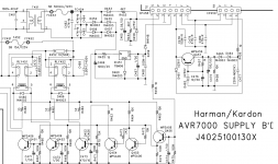
Last year I fixed a newish Harman Kardon sub amp that only powered up into standby. It actually turned out to be a design fault IMHO. There was a mains ripple voltage detection circuit that turned the relays on; the cap in the relevant filter circuit was 1uF and my calculations showed if it was below 0.9uF the circuit couldn't work so I changed it for a 2.2uF and it's been fine since.
The amp powered up without that DTS and video board in when I was working on that board.
Then after reassembly, it did not. Then I pulled the dts and video boards off and it still wont power up. I tried to power it on with every connection I disconnected, and still nothing. Up until now I had pulled everything apart and still not come out of standby.
The last step was to get the front board apart in case the tact switch wasn't working.
I have determined it is fine, so my choice now is to get the ideas you guys gave me, past that I guess I give up.
Cool.
Srinath.
- Status
- This old topic is closed. If you want to reopen this topic, contact a moderator using the "Report Post" button.
- Home
- Amplifiers
- Solid State
- What does +3v3a mean in a schematic