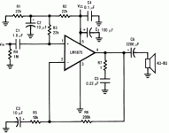
Hello,
I am putting together an amplifier as a final project for a class that is required by my associates degree in Electrical Engineering Technology. I have included an image of the circuit I am using with this post. My measured upper and lower frequency cutoffs are 20Hz and 76KHz. It would be amazing for me to theoretically determine the frequency response of this circuit. I am pretty sure the 1 ohm resistor and the .22uF capacitor are responsible for the upper frequency cutoff. I have absolutely no idea how to organize the portion of the circuit that provides the input bias. I have a feeling that it is responsible for the lower frequency cutoff. Can someone please steer me in the direction of an online resource or a technique that I can use to match my experimental results to my theoretical results.
Thank You,
JMac
Attachments
Hi,
For the high pass its 1uF in series with all the loop resistances to virtual or real earths.
That looks like (22K + 22K||22K)||1M = 32Kohm with 1uF for the high pass function
at the input, but the feedback loop has another, 10uF and 10K||200K = 9.1kohm.
Still I can't get to an estimate of -3dB at 20Hz. Try a sim like the great free TinaTi.
rgds, sreten.
Last edited:
@sreten
The 10uF capacitor C2 doesnt short R1.
Then what about the 0.1uF capacitor?
The 10 uF cap shorts R1 and R2 at audio frequencies, theoretically
The junction of R1, R2, and R3 is at ground potential at audio frequencies, theoretically.
The 0.1 uF cap is a power supply pin bypass.
The input impedance at audio frequencies is 22K, theoretically.
Last edited:
@ Fast Eddie
I agree with your assessment of the input impedance at audio frequencies. The lower frequency cutoff I measured was definitely between 15Hz and 22Hz. If my measurements are not off I'm in error by about 10Hz. When I use 22k compared to 1uf for calculation of frequency attenuation. it's a 1 credit course atleast.
I agree with your assessment of the input impedance at audio frequencies. The lower frequency cutoff I measured was definitely between 15Hz and 22Hz. If my measurements are not off I'm in error by about 10Hz. When I use 22k compared to 1uf for calculation of frequency attenuation. it's a 1 credit course atleast.
Indeed. What is the input impedance of the 1875? I could not find it. It's probably low, but not that low. How about the tolerance on the input cap?
You can lower the low frequency cutoff by increasing the 1 uF capacitor if you like. Try a 2.2 uf cap instead. Are you using an electrolytic? You can get away with using an electrolytic input cap in a single supply amplifier. And you could beef up the "virtual ground" too with a bigger electrolytic (not too big) and a 0.1 uF cap in parallel with the electrolytic.
You can lower the low frequency cutoff by increasing the 1 uF capacitor if you like. Try a 2.2 uf cap instead. Are you using an electrolytic? You can get away with using an electrolytic input cap in a single supply amplifier. And you could beef up the "virtual ground" too with a bigger electrolytic (not too big) and a 0.1 uF cap in parallel with the electrolytic.
- Status
- This old topic is closed. If you want to reopen this topic, contact a moderator using the "Report Post" button.
- Home
- Amplifiers
- Chip Amps
- LM1875 Single Supply Bandwidth
