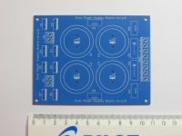
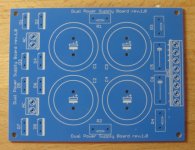
Due canceled project, I have a larger quantity ( around 40 ) of high quality bare PCB amplifier power supply boards available made by local manufacturer. Dimensions are 83x108 mm. 105 um thick copper traces. It supports dual rectification per channel, optional snubber filter, CRC filter. Maximum capacitor diameter is 30 mm.
Price for board is 6 EUR + post costs.
I can supply suitable diodes (NXP BYW29E-200, 0.4 EUR each) and capacitors (Nichicon KG Gold Tune 4700uF/50V, 3.5 EUR each)
You can post offer here or here: moonaudio (at) gmail.com
Price for board is 6 EUR + post costs.
I can supply suitable diodes (NXP BYW29E-200, 0.4 EUR each) and capacitors (Nichicon KG Gold Tune 4700uF/50V, 3.5 EUR each)
You can post offer here or here: moonaudio (at) gmail.com
Attachments
Last edited:
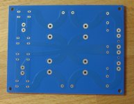
BOM recommendation: Diodes D1-D8 should be TO 220 case diodes of your choose. I have a larger quantity of NXP (Philips) BYW29E-200 too. R1&R2 could be either short circuit or MPC71 0.22 ohm. Optional snubber circuit (R3-C5; R4-C6) consist of 1 ohm resistor MPC71 and 100 nF MKT cap.
How many amps is it rated for?
You mean diodes current rating, correct? With these diodes I have 8A.
http://www.nxp.com/documents/data_sheet/BYW29E-200.pdf
You mean diodes current rating, correct? With these diodes I have 8A.
http://www.nxp.com/documents/data_sheet/BYW29E-200.pdf
No, I mean the board itself. What's the maximum current that the traces on the board can handle before there is significant heating or damage of the board? Or, to put it another way, what's the equivalent wire gauge for the board traces? I would want at least 14 gauge (U.S. size, which is about 2mm^2 metric cross sectional area). 14 gauge in America can handle up to 15 amps without damaging the insulation.
What's the maximum current that the traces on the board can handle before there is significant heating or damage of the board?
The traces are wide 6 mm and thick 105um, that means surface area is around 0.63 mm2. Since traces are short, they can conduct 8A continuous without any problems. 8A is also a max. current most TO-220 diodes can handle. But since most amplifier operate on music and not continuous (sine) signals, pcb traces can handle much more transient current through then.
Using PCB trace calculator, I get final data: 10A continous!!! each rail (6.24mm wide, 105um thick), for ambient T of 25C and Trise of 10C. That mean almost 20A both rails together.
This is more than enough for most diy amplifiers around...
OK, that's great. How much are they and how much is shipping to America (zip code 22407)?
With no heat sink , is it true that the diode might handle approximately 3A continuous at a junction temperature of 150 Deg C ?
Reaching 8A is not possible under any reasonable heat sink configuration ?
This pcb was optimized for small class A or medium to high power class AB amplifiers. The arrangement of using 4 diodes per rail, halved the current flowing through each diode, but adding a small voltage loss on two additional diodes.
I use each this pcb psu for powering 100W/8, 200W/4 mono amplifier. At high listening levels (+-50V DC supply, Troom=20C), diodes get barely warm.
I designed this pcb for AB amplifier project, with minimum foot print possible. I think in 95% of diyers heatsink will not be needed. Those who might want run this diodes on higher currents, will probably also needed large power supply capacitors (>30mm dia) which will not fit on the boards.
- Status
- This old topic is closed. If you want to reopen this topic, contact a moderator using the "Report Post" button.
- Home
- Group Buys
- High quality PCB board for amplifier power supply - group buy