Hello everybody!
First, I have read through a lot of different threads, but haven't found exactly what I was looking for.
As I didn't want to hijack several threads, I decided to start a new one.
I already have successfully designed and built some microcontroller circuits, but I'm quite new to audio design.
Now I want to build a small amp do drive (diy) PC speakers, and I have chosen the popular LM3886.
I generally like my projects being reusable, so everything that could be of use later on should be included.
I hope this was enough background information, so let's start with my questions:
")
PS: I'm not into that high-end-voodoo-thing, I just want to build an optimal, reasonable and stable design.
First, I have read through a lot of different threads, but haven't found exactly what I was looking for.
As I didn't want to hijack several threads, I decided to start a new one.
I already have successfully designed and built some microcontroller circuits, but I'm quite new to audio design.
Now I want to build a small amp do drive (diy) PC speakers, and I have chosen the popular LM3886.
I generally like my projects being reusable, so everything that could be of use later on should be included.
I hope this was enough background information, so let's start with my questions:
- I want to follow the design notes written here: http://www.diyaudio.com/forums/chip-amps/219716-lm3886.html#post3165612 and here: http://www.diyaudio.com/forums/chip-amps/219716-lm3886-3.html#post3167216
Ok, or not? - For supply bypassing, I have planned 470µF per rail (Panasonic FR, 50V, low-ESR) and 100nF X7R ceramic in 0805 SMD case.
- Cc (220pF) is connected between the inputs of the LM3886, but some said it would be better between non-inverted input and GND, so I will provide space for both options.
I planned to use NPO ceramic in 0805 SMD case, is that ok or should it better be foil, mica or something else? - For Ci, the LM4780 datasheet specifies polarized electrolytic capacitor.
Is that correct, or should a non-polarized capacitor type (bipolar electrolytic, foil) be used? - For the snubber (Rsn 2.7R and Csn 100nF), the LM4780 datasheet states 0.25W resistor and ceramic capacitor.
Is the resistor rating ok? In many designs a 2W or 3W resistor is used...
For capacitor, I planned to use X7R ceramic in 0805 case, is that ok or should it be a foil type? - For the Zobel network (10R || 0.7µH in series to the load) there are no ratings and recommendations in the datasheet.
What should be the power rating for the resistor, would 2W be sufficient?
How should the inductor be made?
Pure air core, or wrapped around the resistor? I have read somewhere it should be separate, but don't find it anymore...
PS: I'm not into that high-end-voodoo-thing
, I just want to build an optimal, reasonable and stable design.Ordinary polarised electrolytics are good enough for Ci. But, you must ensure they have virtually no AC across them. i.e. make them big enough (low AC impedance) and any distortion becomes unmeasurable.
If the amplifier never oscillates then the Rsn can never get hot.
If you intend "testing" the amplifier at high frequency, such that you end up "driving" a signal through Rsn, then you may want to make it big enough for however much power you intend to dissipate in it. That could be 60W of continuous 100kHz !
The Rsn + Csn = output Zobel.
Thiele proposed a different stability enhancing Network that had both the Zobel and an output inductor. I refer to this as the Thiele Network. Dr Cherry did more work in explaining the Thiele Network and the infinite variations that can exist.
The amplifier can only heat up the Thiele Network for similar abuse as explained earlier. Do you plan to amplify >100kHz signals?
R//L pure air core. Keep the air core away from the amplifier stage and if possible away from steel chassis. Run the R outside the coil, not through it. I have not seen data for the effect of running the resistor inside the coil, so I'm recommending "play safe".
Last edited:
- For supply bypassing, I have planned 470µF per rail (Panasonic FR, 50V, low-ESR) and 100nF X7R ceramic in 0805 SMD case.
- Cc (220pF) is connected between the inputs of the LM3886, but some said it would be better between non-inverted input and GND, so I will provide space for both options.
I planned to use NPO ceramic in 0805 SMD case, is that ok or should it better be foil, mica or something else?
- For Ci, the LM4780 datasheet specifies polarized electrolytic capacitor.
Is that correct, or should a non-polarized capacitor type (bipolar electrolytic, foil) be used?
- For the snubber (Rsn 2.7R and Csn 100nF), (...) For capacitor, I planned to use X7R ceramic in 0805 case, is that ok or should it be a foil type?
BTW I've never been convinced by that PS, read here.
Ah ok.Ordinary polarised electrolytics are good enough for Ci. But, you must ensure they have virtually no AC across them. i.e. make them big enough (low AC impedance) and any distortion becomes unmeasurable.
I thought of using a bipolar or un-polarized cap because the output swings around GND, and so will the voltage the cap sees.
I planned to make Rin=22k and Cin=4.7µF, which results in a corner frequency of ~1.5Hz.
Ri will be 1k and Ci=180µF, which results in a corner frequency of ~0.9Hz.
I hope this will be big enough, or am I wrong?
Sounds logical.If the amplifier never oscillates then the Rsn can never get hot.
But how can I prevent the amp from oscillating?
Is it just the component placement?
Or can I do anything more to achieve this, like the optional components Rf2 and Cf?
By the way, the formula for the corner frequency of that network is specified in the datasheet as follows:
fc=[Rf1 Rf2 (s + 1/Rf2Cf)]/[(Rf1 +Rf2)(s + 1/Cf(Rf1 +Rf2))]
What is "s"?
Excessive "testing" beyond audio frequencies is not my intention.If you intend "testing" the amplifier at high frequency, such that you end up "driving" a signal through Rsn, then you may want to make it big enough for however much power you intend to dissipate in it. That could be 60W of continuous 100kHz !
The (worst case) 60W of dissipation, when the snubber becomes active, has lead to my question of a reasonable size.
But as I think about it, IF the amp oscillates, it fries the resistor whichever power rating it may have.
So it is quite important (at least for me) to prevent the amp from ever oscillating, as I want an audio amplifier and no RF source.
So the R|L should not be placed on the board?R//L pure air core. Keep the air core away from the amplifier stage and if possible away from steel chassis. Run the R outside the coil, not through it. I have not seen data for the effect of running the resistor inside the coil, so I'm recommending "play safe".
@ClaveFremen:
Those Elna RJH seem not very well available...
I'll have a look at the other types you suggested, and at your thread.
Good night!
The NFB DC blocking cap has a very small DC voltage across it.
This DC voltage is due to the input offset voltage of the amplifier. This input offset voltage exists at BOTH the +IN and -IN inputs.
The AC voltage across the DC blocking cap should be very small and the peak voltage is likely to be less than the DC bias across it. This addition of two very small voltages is usually never a -ve bias across the polarised capacitor.
In addition some of the polarised capacitor manufacturers state that a reverse voltage of < ~1Vdc is OK for their capacitors.
I can see that when the DC blocking capacitor is too small and thus develops a significant AC voltage across it that the added distortion of that too small capacitor will have an audible effect. I suspect that many have heard this and without realising the cause concluded that the NFB DC blocking capacitor has a "sound" effect.
When the capacitor is sized such that there is virtually no signal voltage across it then the distortion added by the capacitor is inaudible.
This is something I have found in practice. I cannot hear the "sound" changes alluded to by other builders.
This DC voltage is due to the input offset voltage of the amplifier. This input offset voltage exists at BOTH the +IN and -IN inputs.
The AC voltage across the DC blocking cap should be very small and the peak voltage is likely to be less than the DC bias across it. This addition of two very small voltages is usually never a -ve bias across the polarised capacitor.
In addition some of the polarised capacitor manufacturers state that a reverse voltage of < ~1Vdc is OK for their capacitors.
I am very inclined to not agree this quality philosophy.That cap, if dimensioned like Andrew suggest, has a neglegible distortion contribute but its signature, IMHO, is still audible, use an audio grade cap (Nichicon FG is fine)
I can see that when the DC blocking capacitor is too small and thus develops a significant AC voltage across it that the added distortion of that too small capacitor will have an audible effect. I suspect that many have heard this and without realising the cause concluded that the NFB DC blocking capacitor has a "sound" effect.
When the capacitor is sized such that there is virtually no signal voltage across it then the distortion added by the capacitor is inaudible.
This is something I have found in practice. I cannot hear the "sound" changes alluded to by other builders.
Last edited:
Thank you for the explanation AndrewT, I really appreciate your help!
I have read a lot from you in other LM3886 threads.
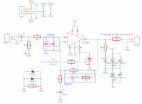
Here is what I have done until now.
The schematics is still a bit messy, because I have changed it several times after studying several design "guidelines".
The color codes for the layout are:
Red: top copper layer
Green: bottom copper layer
Cyan: top silkscreen layer
Magenta: bottom silkscreen layer
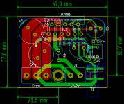
The parts were selected from the available types at Conrad and Reichelt, two popular german parts suppliers.
They may still change, but here is what was used for creating the current layout:
Cs (C1, C4): Panasonic FR 470µF 50V; (C3, C5): ceramic X7R 100nF
Ci (C2): Panasonic FC 180µF 50V
Cin (C10): Wima MKS-2 4.7µF
Cm (C6): Panasonic FC 100µF 50V
Cc (C8, C11): ceramic NPO 220pF
Cf (C9): ceramic NPO 47pF
Csn (C7): ceramic X7R 100nF
Rsn (R6): Yageo RC1206 2.7R 0.25W
Output resistor+coil (R9): will be removed from PCB
other resistors: metal film 0805
What do you think of my attempt?
Regards
I have read a lot from you in other LM3886 threads.
Here is what I have done until now.
The schematics is still a bit messy, because I have changed it several times after studying several design "guidelines".
The color codes for the layout are:
Red: top copper layer
Green: bottom copper layer
Cyan: top silkscreen layer
Magenta: bottom silkscreen layer
The parts were selected from the available types at Conrad and Reichelt, two popular german parts suppliers.
They may still change, but here is what was used for creating the current layout:
Cs (C1, C4): Panasonic FR 470µF 50V; (C3, C5): ceramic X7R 100nF
Ci (C2): Panasonic FC 180µF 50V
Cin (C10): Wima MKS-2 4.7µF
Cm (C6): Panasonic FC 100µF 50V
Cc (C8, C11): ceramic NPO 220pF
Cf (C9): ceramic NPO 47pF
Csn (C7): ceramic X7R 100nF
Rsn (R6): Yageo RC1206 2.7R 0.25W
Output resistor+coil (R9): will be removed from PCB
other resistors: metal film 0805
What do you think of my attempt?
Regards
Attachments
@ClaveFremen:
Those Elna RJH seem not very well available...
I'll have a look at the other types you suggested, and at your thread.
You can buy them in Germany from Distrelec
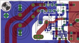
What do you think of my attempt?
I would trasnfer PGND to the other side or to a groundplane so that you can route differently several traces like the ones related to mute pin and V+.
Something like that:
As you can see V+ doesn't overlap OUT
Attachments
Thank you for the hint!You can buy them in Germany from Distrelec
Do they stock the other types you mentioned as well?
The site is down at the moment...
I have left them intentionally on the same side, because of the SMD bypass caps I use at the moment.I would trasnfer PGND to the other side or to a groundplane so that you can route differently several traces like the ones related to mute pin and V+.
But I could trim the ground polygon under the IC, and place the V+ track under the IC (where the ground trace is at the moment).
How would that be?
I don't like the crossing of V+ and Output either.
But sometimes I need to get a hint from someone else to see a solution.
Thank you for the hint!
Do they stock the other types you mentioned as well?
The site is down at the moment...
You're welcome.
They stock Wima FKP2 (use 2.5% tolerance -> copper leads, better if 100V rated)
I have left them intentionally on the same side, because of the SMD bypass caps I use at the moment.
You can use vias... or use LM3886 pads as vias...or simply bypass rail to rail like I did...
But I could trim the ground polygon under the IC, and place the V+ track under the IC (where the ground trace is at the moment).
How would that be?
Post a picture...
I don't like the crossing of V+ and Output either.
But sometimes I need to get a hint from someone else to see a solution.
The V+ trace would just look like yours, and Gnd trace would end between the SMD decoupling capacitors.You can use vias... or use LM3886 pads as vias...or simply bypass rail to rail like I did...
Post a picture...
Has the rail to rail bypassing any advantages over bypassing each rail to ground?
Ah, I've found them.They stock Wima FKP2 (use 2.5% tolerance -> copper leads, better if 100V rated)
But sadly they don't have a 47pF or 56pF type, as is needed for Cf...
And SMD types like Panasonic EHCU are also not available, but Reichelt has them only in 330pF and 470pF, and also 100nF.
Will the 100nF EHCU be ok for power bypassing and Csn?
Are Wima MKS-2 ok for NF input?
And are the Elna RJH also ok for Ci?
Because Distrelec doesn't have any Nichion caps.
Has the rail to rail bypassing any advantages over bypassing each rail to ground?
It depends on the sort of noise you want to filter, common mode noise should be better filtered by rail to rail caps.
But sadly they don't have a 47pF or 56pF type, as is needed for Cf...
And SMD types like Panasonic EHCU are also not available, but Reichelt has them only in 330pF and 470pF, and also 100nF.
Silver mica then, for such values.
You can buy them from RS Components (you'll find also ECHU).
(CDE MC series)
Will the 100nF EHCU be ok for power bypassing and Csn?
Sure, choose the correct voltage rating, obviously.
Are Wima MKS-2 ok for NF input?
They're better than elcos, unbeatble for the 5mm lead spacing but using bigger caps you can have a much better quality sound.
And are the Elna RJH also ok for Ci?
Because Distrelec doesn't have any Nichion caps.
You can order audiograde caps (including nichicons) from HifiCollective (GB).
I would not use RJHs for Ci
Why?...............I would not use RJHs for Ci
What capacitor parameters make that selection unsuitable?
@ClaveFremen: Thanks for the advice, I will go through the stocks of that shops to see if they have the parts I need.
For the NF input caps: If they are the best in that size range, I think I will use them.
I have seen the sizes some others use, they are bigger than my whole PCB.
I have mentioned it earlier already: The source for this amp will be my PC.
Would using any "high-end" capacitors even make sense?
Because I cannot imagine my onboard audio was designed by audiophiles...
I don't mind trying out something like the Elna caps instead of Panasonic for PS decoupling, because thy are reasonably priced.
And if I can achieve good results with them, why not.
But I definately won't use any brick-sized capacitor-thingies which were made by virgins at full moon and sanctified by a voodoo priest, sold for the price of a mansion.
I don't say that to offend anybody here (just to be clear), I just don't like paying way too much (in my eyes) for any product.
Here's my new approach for the power supply routing.
Better? Worse?
Somehow I'm not quite sure if I like it or not...
Attachments
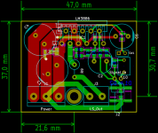
I have redesigned the power supply bypassing again.
It now looks a bit more like the screenshot from ClaveFremen, thanks again for the pic!
I have also added a ground plane for Signal Ground, which only connects at the signal ground star point (located at the NF input).
What do you think about it?
Regards, Stefan
It now looks a bit more like the screenshot from ClaveFremen, thanks again for the pic!
I have also added a ground plane for Signal Ground, which only connects at the signal ground star point (located at the NF input).
What do you think about it?
Regards, Stefan
Attachments

Way is your plans for the power supply? Consideration of how you will power your LM3886 chip modules you are building here is probably as important as anything else you are working on here. CarlosFM's snubberized PSU design is as popular as they get around here...I personally prefer the regulated supply he designed, either one is an excellent choice.
Yes, the output Zobel is located under C1.is there an output Zobel fitted?
A MELF resistor connecting at the output trace and crossing the V+ trace, and a 0805 capacitor.
I have marked it (blue rectangle) in the attached picture.
Is the placement ok?
I moved down the row of SMD parts for about 1.4mm, to make room for an alternative footprint for C9 (Cf).The HF decoupling route looks as though it is a bit longer.
Stupidly, I didn't find any SMD capacitors in the 50pF range other than ceramics (C0G or NPO).
So, if I want to use a foil type for Cf, I will have to pick a THT part.
But I could move the other parts back upwards, where they were before.
Would that be better?
I initially planned to use the unregulated CarlosFM design and read the whole thread about it.Way is your plans for the power supply? Consideration of how you will power your LM3886 chip modules you are building here is probably as important as anything else you are working on here. CarlosFM's snubberized PSU design is as popular as they get around here...I personally prefer the regulated supply he designed, either one is an excellent choice.
But then I came across the explanations of Rainwulf here on page 65: http://www.diyaudio.com/forums/chip-amps/43423-high-cap-unregulated-psu-chipamps-65.html#post1761186
This sounds very reasonable for me, so I think I will follow these guidelines.
Attachments

It now looks a bit more like the screenshot from ClaveFremen, thanks again for the pic!
You're welcome, Stefan
I have also added a ground plane for Signal Ground, which only connects at the signal ground star point (located at the NF input).
Maybe you could separate signal ground from powerground with a low value resistor (1-10 Ohm).
Andrew, what do you think about it?
Yes, the output Zobel is located under C1.
(...)
Is the placement ok?
Sincerely I don't like it much... you can possibly pollute PS lines with amp's output...
The zobel, IMHO, should go away from the groundplane.
Also try to isolate LM3886's OUT from groundplane (same reason).
I woudl suggest you to enlarge a bit the board.
So, if I want to use a foil type for Cf, I will have to pick a THT part.
It wouldn't be tragedy, IMHO
The two grounds are already separated by a resistor (R8) and two anti-parallel diodes (D1, D2). The connection point is located in the lower right corner, right from the output terminal, and under the input connector.Maybe you could separate signal ground from powerground with a low value resistor (1-10 Ohm).
Interesting, as I think about it, I'm more concerned about the Zobel resistor picking up noise from the V+ trace and leading it back to the feedback input.Sincerely I don't like it much... you can possibly pollute PS lines with amp's output...
What about if I rotate the Zobel by 90°, so that it would go downwards instead of left?The zobel, IMHO, should go away from the groundplane.
Ok, I will cut the plane over the output trace.Also try to isolate LM3886's OUT from groundplane (same reason).
Sure, but I wonder why such low-value capacitors are not available as SMD.It wouldn't be tragedy, IMHOSo, if I want to use a foil type for Cf, I will have to pick a THT part.
I think, especially these are predestinated for SMD, to get rid of the influences of the terminal legs.
But for example the ECHU series is available from 100pf on.
- Status
- This old topic is closed. If you want to reopen this topic, contact a moderator using the "Report Post" button.
- Home
- Amplifiers
- Chip Amps
- LM3886 component selection