Hello
Please look at my project of audio mixer.
It should work as portable audio device, battery powered.
12v through Traco Power TEN-5 1223: +/-15V +/-200mA
First stage is SSM2019 - work as mic preamplifier with 48V phantom...
Next 10k log Pot as volume for channel 1.
There will be the same 3 channels. I didn't draw it.
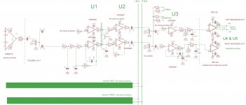
U1 OPA2604 work as low pass filter at unity-gain.
It separate left & right path SSM2019 from PAN Switch.
3 positions shorts L to GND or R to GND or leave both channels untouch.
So, in this way I made simple panorama switch - only 3 positions: L, R, both...
U2 - OPA2604 next unity-gain. It separate all path channel from mix section.
U3 - OPA2604 with U4&U5 DRV134 it's master section with balanced out.
First! Please analyze my project. What is wrong?
Maybe I made some stupid mistakes. Please tell, repair.
It's my first serious job. I need it to work.
So, I can't pay for SQN or other devices...
Please, look at the resistors, capacitors...
Does that make sense?
THX
sng.pol46@gmail.com
Please look at my project of audio mixer.
It should work as portable audio device, battery powered.
12v through Traco Power TEN-5 1223: +/-15V +/-200mA
First stage is SSM2019 - work as mic preamplifier with 48V phantom...
Next 10k log Pot as volume for channel 1.
There will be the same 3 channels. I didn't draw it.
U1 OPA2604 work as low pass filter at unity-gain.
It separate left & right path SSM2019 from PAN Switch.
3 positions shorts L to GND or R to GND or leave both channels untouch.
So, in this way I made simple panorama switch - only 3 positions: L, R, both...
U2 - OPA2604 next unity-gain. It separate all path channel from mix section.
U3 - OPA2604 with U4&U5 DRV134 it's master section with balanced out.
First! Please analyze my project. What is wrong?
Maybe I made some stupid mistakes. Please tell, repair.
It's my first serious job. I need it to work.
So, I can't pay for SQN or other devices...
Please, look at the resistors, capacitors...
Does that make sense?
THX
sng.pol46@gmail.com
Attachments
Where is the rest of it?
The power supply filtering will be critical to keep switchmode converter noise out of everything, to the point that I would take the 6dB hit and run it single supply off the battery rather then sticking a miniture DC/DC in there (At best a switchmode in there is asking for a lot of design effort at layout time)....
How are you generating the 48V for phantom?
The input impedance to your LPF changes depending on the volume setting, probably not what you want?
Input circuit? P48? Protection? RFI Filter? Pad? Phase switch? HPF?
A per channel mute switch would be a good thing.
Where does that third order MFB filter go over (Cannot be bothered to sim it)?
10K master pot feeding a 2.7K input Z buffer will have a very odd control law.
2.2uF into 2K7 impedance, feels like phase shift at LF (Cannot be bothered to do the sums).
What is the thinking behind the network at the output of U3? If you are not going for virtual earth or ground compensated summing then U3 looks largely redundant to me?
Output build out resistors? RFI measures? Transient and phantom protection?
Lets see the whole schematic, this is barely more then a block diagram.....
And the elephant in the room, board layout! All those pretty little 'GND' symbols hide IMPORTANT detail.
Get Doug Selfs book on small signal audio design, it contains much that is interesting for mixing desks.
Regards, Dan.
Thank You so much for Your efffort.
I'm just a humble sound recordist, who can not afford the expensive professional equipment.
1. Power supply: battery 12V to +/-15V by: www.tracopower.com/products/ten5.pdf
with some external capacitors - TEN5-1223. I didn't test it yet, but I have one.
Maybe I should to run it with some oscilloscope to check...
You wrote about single supply... Last step makes balanced line signal.
I found DRV134 - I think it should be run with +/- supply.
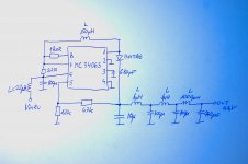
2. The 48V: MC 34063 - attachment
3. "The input impedance to your LPF changes depending on the volume setting, probably not what you want?"
How can I achieve the goal in a different way?
4. "Input circuit? P48? Protection? RFI Filter? Pad? Phase switch? HPF?"
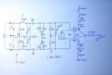
I attached scheme with first step of mixer. LPF, HPF, protection by diodes LED...
5. "A per channel mute switch would be a good thing."
How to do this? How to apply Your idea?
You mean the option of removing the pan switch?
...or "Mute Switch" should be apply before Pan Switch?
6. "Where does that third order MFB filter go over (Cannot be bothered to sum it)?"
Don't understand. You mean U3 as Multiple Feedback Bandpass Filter?
7. 10K master pot feeding a 2.7K input Z buffer will have a very odd control law.
2.2uF into 2K7 impedance, feels like phase shift at LF (Cannot be bothered to do the sums).
I should rise the value of those 2k7? or maybe 2,2u replace with 1u?
I just wanted to put only some preamp before DRV134.
8. What is the thinking behind the network at the output of U3? If you are not going for virtual earth or ground compensated summing then U3 looks largely redundant to me?
LPF. Again. Not?
9. "Output build out resistors? RFI measures? Transient and phantom protection?"
Don't understand at all")
You mean output protection?
Output protection against high frequencies deriving from phantom supply?
10. "And the elephant in the room, board layout! All those pretty little 'GND' symbols hide IMPORTANT detail."
I will remember this for lifetime
What kind of 'details' You mean?
What to look for when designing board?
11. The Audio Power Amplifier Design Handbook - I will...
12. I use U2 & U3 for separate "mix section" from:
- Pan Switch
- DRV134
If I should achive this in some different way, please help.
Maybe I can get rid of some amps...?
13. I'm not sure that idea of Pan Switch is good.
I don't want to use potentiometers. Channel selection should be simple.
I collected this idea/scheme of several components.
I have a problem with the fit to each individual blocks.
I know that it's very hard, I think for me, so I hope on your help.
I can not afford to buy expensive equipment SQN SQN ENG Mixers: Home
so I decided to build my own.
So, If You can help me & redesign my idea/scheme, please do it
I am grateful for the help.
Chris sng.pol46@gmail.com
I'm just a humble sound recordist, who can not afford the expensive professional equipment.
1. Power supply: battery 12V to +/-15V by: www.tracopower.com/products/ten5.pdf
with some external capacitors - TEN5-1223. I didn't test it yet, but I have one.
Maybe I should to run it with some oscilloscope to check...
You wrote about single supply... Last step makes balanced line signal.
I found DRV134 - I think it should be run with +/- supply.
2. The 48V: MC 34063 - attachment
3. "The input impedance to your LPF changes depending on the volume setting, probably not what you want?"
How can I achieve the goal in a different way?
4. "Input circuit? P48? Protection? RFI Filter? Pad? Phase switch? HPF?"
I attached scheme with first step of mixer. LPF, HPF, protection by diodes LED...
5. "A per channel mute switch would be a good thing."
How to do this? How to apply Your idea?
You mean the option of removing the pan switch?
...or "Mute Switch" should be apply before Pan Switch?
6. "Where does that third order MFB filter go over (Cannot be bothered to sum it)?"
Don't understand. You mean U3 as Multiple Feedback Bandpass Filter?
7. 10K master pot feeding a 2.7K input Z buffer will have a very odd control law.
2.2uF into 2K7 impedance, feels like phase shift at LF (Cannot be bothered to do the sums).
I should rise the value of those 2k7? or maybe 2,2u replace with 1u?
I just wanted to put only some preamp before DRV134.
8. What is the thinking behind the network at the output of U3? If you are not going for virtual earth or ground compensated summing then U3 looks largely redundant to me?
LPF. Again. Not?
9. "Output build out resistors? RFI measures? Transient and phantom protection?"
Don't understand at all
You mean output protection?
Output protection against high frequencies deriving from phantom supply?
10. "And the elephant in the room, board layout! All those pretty little 'GND' symbols hide IMPORTANT detail."
I will remember this for lifetime
What kind of 'details' You mean?
What to look for when designing board?
11. The Audio Power Amplifier Design Handbook - I will...
12. I use U2 & U3 for separate "mix section" from:
- Pan Switch
- DRV134
If I should achive this in some different way, please help.
Maybe I can get rid of some amps...?
13. I'm not sure that idea of Pan Switch is good.
I don't want to use potentiometers. Channel selection should be simple.
I collected this idea/scheme of several components.
I have a problem with the fit to each individual blocks.
I know that it's very hard, I think for me, so I hope on your help.
I can not afford to buy expensive equipment SQN SQN ENG Mixers: Home
so I decided to build my own.
So, If You can help me & redesign my idea/scheme, please do it
I am grateful for the help.
Chris sng.pol46@gmail.com
Attachments
Ok, lets see now....
The input stage, 1uF is way too small, something more like 22 or 47uF would be better here.
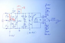
I don't like the LED thing, they act as varicaps, low capacitance TVS diodes do better here, and you might like to consider 10 ohm series resistors in each leg after the phantom blocking caps to limit the current it a mic cable shorts with phantom applied (The cap suddenly discharges into the amplifier input transistor if you are not careful).
Connect a 220uF cap from the junction of the 6K8 resistors to ground, and a 1K resistor from the cap to the phantom switch, it will help to reduce the noise from the 48V switcher getting into the inputs (Also it will reduce the thump when phantom is switched live).
Pin 1 on the XLR and the input RFI caps need to go dirrectly to case ground right at the connector, do not connect these to the general 'reference' ground.
Generally, a high pass filter is actually far more useful then lowpass (It helps to cut down rumble and traffic noise), maybe a 50 or 100Hz switchable second order MFB right after the preamp?
Place a double pole changeover switch between the input caps and the preamp inputs to allow pins 2 & 3 on the XLR to be swapped so you can reverse the polarity of the input. Place a 20dB switchable pad before the mic preamp but after the phantom supply so you can attenuate the input to allow line level inputs to be accomodated.
You need to organise PFL in some fashion, maybe a double pole switch with one side switching the audio from before the volume pot to a PFL bus and the other side switching DC to a 'PFL Selected' bus?
Any reason you are using voltage mode summing? Current summing in a virtual earth bus is usually the obvious choice in small mixers like this.
Give me a few days and I will try to sketch out how I would tackle the thing, it is probably easier.
Regards, Dan.
The input stage, 1uF is way too small, something more like 22 or 47uF would be better here.
I don't like the LED thing, they act as varicaps, low capacitance TVS diodes do better here, and you might like to consider 10 ohm series resistors in each leg after the phantom blocking caps to limit the current it a mic cable shorts with phantom applied (The cap suddenly discharges into the amplifier input transistor if you are not careful).
Connect a 220uF cap from the junction of the 6K8 resistors to ground, and a 1K resistor from the cap to the phantom switch, it will help to reduce the noise from the 48V switcher getting into the inputs (Also it will reduce the thump when phantom is switched live).
Pin 1 on the XLR and the input RFI caps need to go dirrectly to case ground right at the connector, do not connect these to the general 'reference' ground.
Generally, a high pass filter is actually far more useful then lowpass (It helps to cut down rumble and traffic noise), maybe a 50 or 100Hz switchable second order MFB right after the preamp?
Place a double pole changeover switch between the input caps and the preamp inputs to allow pins 2 & 3 on the XLR to be swapped so you can reverse the polarity of the input. Place a 20dB switchable pad before the mic preamp but after the phantom supply so you can attenuate the input to allow line level inputs to be accomodated.
You need to organise PFL in some fashion, maybe a double pole switch with one side switching the audio from before the volume pot to a PFL bus and the other side switching DC to a 'PFL Selected' bus?
Any reason you are using voltage mode summing? Current summing in a virtual earth bus is usually the obvious choice in small mixers like this.
Give me a few days and I will try to sketch out how I would tackle the thing, it is probably easier.
Regards, Dan.
Ok, lets see now....
The input stage, 1uF is way too small, something more like 22 or 47uF would be better here.
I plan to put parallel more capacitors - 8-10 x 1uF
I don't want to use electrolitic...
I don't like the LED thing, they act as varicaps, low capacitance TVS diodes do better here, and you might like to consider 10 ohm series resistors in each leg after the phantom blocking caps to limit the current it a mic cable shorts with phantom applied (The cap suddenly discharges into the amplifier input transistor if you are not careful).
If You have better idea, please share...
Connect a 220uF cap from the junction of the 6K8 resistors to ground, and a 1K resistor from the cap to the phantom switch, it will help to reduce the noise from the 48V switcher getting into the inputs (Also it will reduce the thump when phantom is switched live).
I can imagine it, but if You will draw something, please remember about it. I didn't see anywhere the solution like this, but it might be work
Why there are always 6,8k for 48V?
Those 1k make any difference?
Pin 1 on the XLR and the input RFI caps need to go dirrectly to case ground right at the connector, do not connect these to the general 'reference' ground.
...so, connect it close to connector on the board?
Generally, a high pass filter is actually far more useful then lowpass (It helps to cut down rumble and traffic noise), maybe a 50 or 100Hz switchable second order MFB right after the preamp?
I think I can't make good project of this... Any help?
Yes, pro devices use this solution frequently.
Place a double pole changeover switch between the input caps and the preamp inputs to allow pins 2 & 3 on the XLR to be swapped so you can reverse the polarity of the input.
For what reason make 'reverse polarity function'?
It should be only simple device.
Place a 20dB switchable pad before the mic preamp but after the phantom supply so you can attenuate the input to allow line level inputs to be accomodated.
Important thing! I decided to make line/mic attenuate switch by changing Rg value. So, the amplification will be changed, not attenuate.
I don't know that my project is good in this version.
Maybe better way to make some pad for line/mic & then setting Rg of SSM2019...
You need to organise PFL in some fashion, maybe a double pole switch with one side switching the audio from before the volume pot to a PFL bus and the other side switching DC to a 'PFL Selected' bus?
I don't plan PFL... maybe after I will pass all basic problem...
99% of my work is using one mic.
Any reason you are using voltage mode summing? Current summing in a virtual earth bus is usually the obvious choice in small mixers like this.
If You mean pot 10k with U3 - I don't know any other solution to make mix...
Give me a few days and I will try to sketch out how I would tackle the thing, it is probably easier.
Regards, Dan.
Damn I appreciate Your interest
I really want to help myself at work, but I can't.
Finalize this project help me a lot.
Big thanks! chris
Attachments
- Status
- This old topic is closed. If you want to reopen this topic, contact a moderator using the "Report Post" button.
- Home
- Amplifiers
- Chip Amps
- PORTABLE AUDIO MIXER - judge the project, check...