Hey guys!
Getting ready to repair this big guy and have a couple of questions first.
The amp uses IRF1405 (24 of them ) power supply fets and all need to be replaced. The gate resistors are 10 ohm.
I already have a good stock pile of IRF3205 fets and would like to know if these would make a suitable sub? IRF3205PBF International Rectifier | IRF3205PBF-ND | DigiKey If these would work for a sub, would I need to change the value for the gate resistors?
I would also like a little input as to why there are different part numbers (and specs) for the same model of fets. For example; when shopping for new IRF1405 replacements, Digikey offers: IRF1405ZPBF International Rectifier | IRF1405ZPBF-ND | DigiKey AND IRF1405PBF International Rectifier | IRF1405PBF-ND | DigiKey
Now this is not the first time I've seen this scenario, but I've never really understood why or how there is a difference. In the past, I've simply ordered the more expensive part (really out of ignorance)
Finally, I have noticed that R165 and R97 each have blown. Not sure if anyone has a service manual or schematic... keeping my fingers crossed!
Thanks in advance for the help!
Getting ready to repair this big guy and have a couple of questions first.
The amp uses IRF1405 (24 of them
) power supply fets and all need to be replaced. The gate resistors are 10 ohm.I already have a good stock pile of IRF3205 fets and would like to know if these would make a suitable sub? IRF3205PBF International Rectifier | IRF3205PBF-ND | DigiKey If these would work for a sub, would I need to change the value for the gate resistors?
I would also like a little input as to why there are different part numbers (and specs) for the same model of fets. For example; when shopping for new IRF1405 replacements, Digikey offers: IRF1405ZPBF International Rectifier | IRF1405ZPBF-ND | DigiKey AND IRF1405PBF International Rectifier | IRF1405PBF-ND | DigiKey
Now this is not the first time I've seen this scenario, but I've never really understood why or how there is a difference. In the past, I've simply ordered the more expensive part (really out of ignorance
)Finally, I have noticed that R165 and R97 each have blown. Not sure if anyone has a service manual or schematic... keeping my fingers crossed!
Thanks in advance for the help!
I can't really tell you why digi-key has two different spec's for the same part number. I would call them about it myself. Original factory fets were a 80N06 device likely a RFP, or STP heading. The IRF3205 should do nicely as a upgraded part replacement. I think someone else put those fets you see in it now, althoufgh I have seen them in these they were not the original mosfet device.
But I can tell you all of these amps had a serious issues with the differential noise filter toroid shorting out. < I had a friend with a whole pallet of the factory return boards and all of them had the shorted toroid/blown power supply issue.
Esoteric/Diamond Audio apparently just replaced the whole amp board when this failure occurred. > So you should be on the look out for a bad filter toroid short issue, and it sometimes does not show up at idle power levels < my personal experiences on these >. Only when the amp is pushed to higher power levels does the short occur and the whole power supply will blow out like your describing in your repair..
Just some observations from my memory to help you to avoid some rework. I had one of these do this to me. Ran perfectly at idle and low power and at higher output it would short out and blow out the power supply completely... hope this helps some....
PM me directly about the schematic info
Last edited:
i don't remember exactly what, but there is usually a big enough difference with the "z" designation, that it probably won't swap well. that aside, often times, if you look close enough at all the different parts listed for the same part, there will be that many because of case and package type, as well as different minimum quantities. then, of course, different manufacturers. if you are unsure about a part, pick one closest to your aplication, and click the little tiny "D" that resembles "square d" symbol at the far right, pasty the unit price. it is the quick link to the product sheet.
Thanks for the reply.
I undrstand that there may be several different casing styles and or brand for the same part/model. I also check the data sheets.
Occasionally though, like the two examples in the link above, there are slight variants of the same part even though they are from the same manufacturer AND even the same casing (to220 in this scenario) Yet the specs are different between the two.
blah, hopefully that made sense. I literaly just woke up and havn't finished my coffee yet..lol
Making a little progress with this amp. Big thanks to 1moreamp for the help and info.
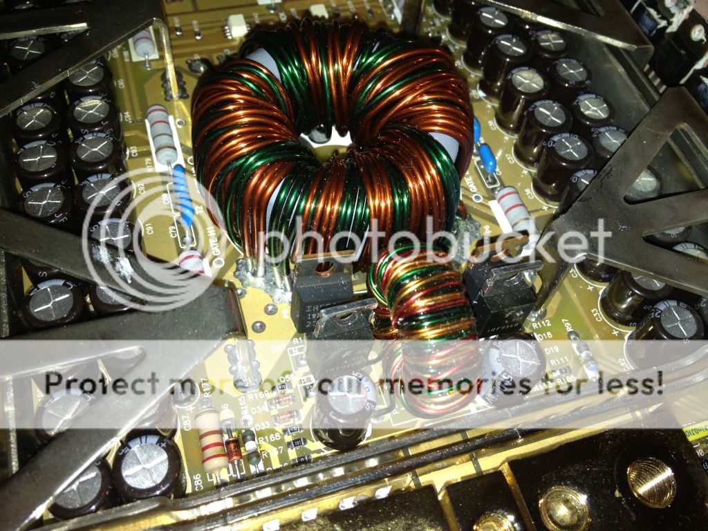
So I've learned that this amp uses an H-bridge power supply and has a dedicated gate drive circuit utilizing a small transformer/fet combo.
Here's a pic of that drive circuit:
I now have the power supply up and running, but if you can see from the pics below, some of the gates are seeing a higher drive signal than others. I'm not sure if this is acceptable or not?
Gate High 1:
Gate High 2:

Gate Low 1:

Gate Low 2:

I havn't seen this before so I'm just trying to see if this is a common result for this type of drive circuit or if I should investigate further.
Thanks
So I've learned that this amp uses an H-bridge power supply and has a dedicated gate drive circuit utilizing a small transformer/fet combo.
Here's a pic of that drive circuit:
I now have the power supply up and running, but if you can see from the pics below, some of the gates are seeing a higher drive signal than others. I'm not sure if this is acceptable or not?
Gate High 1:
Gate High 2:
Gate Low 1:
Gate Low 2:
I havn't seen this before so I'm just trying to see if this is a common result for this type of drive circuit or if I should investigate further.
Thanks
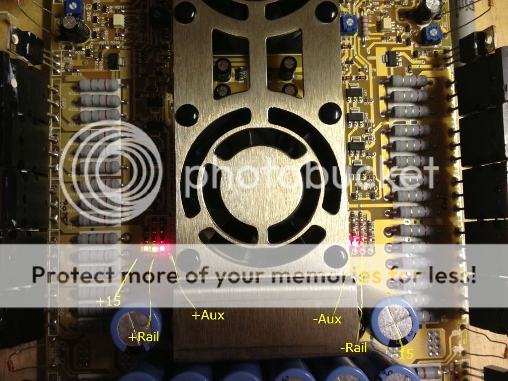
So here's another anomoly that has me a bit baffled. I currently have all 8 of the MUR1520 rectifiers removed from the amp (one of them was shorted), yet there is still significant voltage present for the Positive half of the rail voltage (~54v). When metering contact points for the Neg rail voltage I get ~ -4.6v
Here you can see the led indicators that the amp provides for +&- 15v, Pos & Neg rail voltage, and Aux voltage
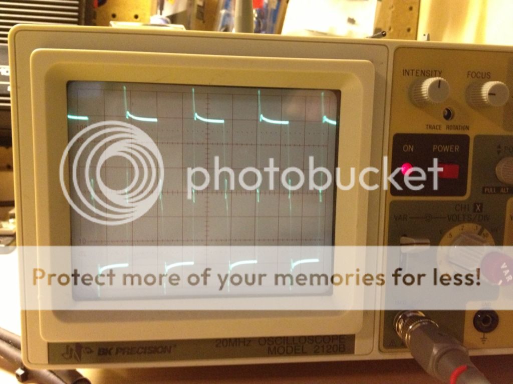
Here are the signals coming "from" the transformer to the input pads of the rectifiers:
(All inputs are identical in waveform and voltage)
Time base = 10us
Volt/div = 2v
Probe = X10

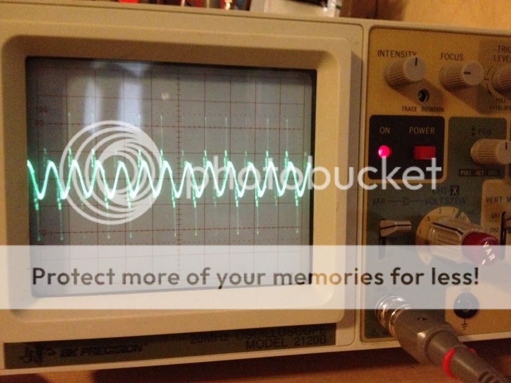
And here is some sort of oscillation coming from/through the filtering inductors. (rectifiers still removed)
Time base = 10us
Volt/div = 0.5v
Probe =X1
Here you can see the led indicators that the amp provides for +&- 15v, Pos & Neg rail voltage, and Aux voltage
Here are the signals coming "from" the transformer to the input pads of the rectifiers:
(All inputs are identical in waveform and voltage)
Time base = 10us
Volt/div = 2v
Probe = X10
And here is some sort of oscillation coming from/through the filtering inductors. (rectifiers still removed)
Time base = 10us
Volt/div = 0.5v
Probe =X1
Last edited:
- Status
- This old topic is closed. If you want to reopen this topic, contact a moderator using the "Report Post" button.
- Home
- General Interest
- Car Audio
- Diamond Audio D7402 w/ blown power supply