so the F5T looks great, especially the V3 version,
but i realized this would be overkill for my needs,
what i would ideally like, is decent power in to lower impedance,
as you know most 8 ohm speakers dip to ~4 ohms through part of their frequency range,
many 4 ohm speakers dip to 2 ohms or less due to the passive crossover.
so while the F5T V1 has enough power, i'd like to maintain the power into low impedance,
is it as simple as paralleling more output devices, and increasing Bias?
i'll try to attach a schematic of my suggestion.

true, but a 16A relay should do?
one set of contacts per FET,
should only need to handle a couple of amps.
but it would certainly be a switch over when powered off,
maybe even a plug in connector to connect the other 1/2 output devices.
is the idea generally sound though for the 4 ohm F5T, or is it better to base it of the V3 with diodes bypassing the 1R's
is it recommended to cascode the input devices or not with 32v supplies?
sorry for all the questions.
in return feel free to ask away on the fine detail of driver/transducer design!
if you need more current , just go with normal rails but with diodes parallel to Rs
3 pairs of output , biased appropriately , will cover all sane needs
anyway - I can't imagine that you're going to use one day easier , another day harder speakers , to drive with same amp .
3 pairs of output , biased appropriately , will cover all sane needs
anyway - I can't imagine that you're going to use one day easier , another day harder speakers , to drive with same amp .
ok,
so based on V3 but lower voltage rails about +/- 32v.
keep the input cascode?
my speakers change fairly frequently, I design drivers for a living!
but yes, not every day")
it would be good to built it with perhaps 4 pairs, and have pairs 3 and 4 (relatively) easy to disconnect,
that way i'm not filling the room with heat if i have 10-16 ohm speakers,
but i'm still ok if i have a 4ohm speaker the next month.
so based on V3 but lower voltage rails about +/- 32v.
keep the input cascode?
my speakers change fairly frequently, I design drivers for a living!
but yes, not every day
it would be good to built it with perhaps 4 pairs, and have pairs 3 and 4 (relatively) easy to disconnect,
that way i'm not filling the room with heat if i have 10-16 ohm speakers,
but i'm still ok if i have a 4ohm speaker the next month.
if you design drivers for living , it's not insane to have 2 different amps
whatever - if you are not in mood for that , idea with additional output pairs is doable , but you must arrange those additional ones from same matched groups as stationary ones
and be careful to observe potential difference in output offset , between just stationary vs. stationary + additional
input cascode is , for my experience , beneficiary even for regular version
ok, thanks very much for the feedback,
if the amp needs re-adjusting then this would be annoying (although not impossible)
as for multiple amps, i would love to.... but as it is i get enough distortion in my ear because i change speakers a lot,
having spare amplifiers would equal much more distortion from an already very tolerant girlfriend
.....
if the amp needs re-adjusting then this would be annoying (although not impossible)
......
if you arrange matched outputs as I already wrote , that doesn't need to be major issue , or issue at all
Cascode is generally to reduce dissipation in higher voltage versions of the F5t.
Low impedance drive capability generally does not suit high supply rails.
My conclusion from those two very general assumptions, is that cascodes are not for improving low impedance drive capability.
Back to your current vs passive crossover speakers.
The resistive low impedance dip is not the worst case for current demand. That is generally around 60% to 80% of the nominal speaker impedance, if the manufacturer has been honest in rating the speaker impedance.
The worst case is for fast starting or fast stopping transients.
These worst case music signals can result in speaker current demand approaching 5 (five) times that indicated by the nominal speaker impedance.
i.e. a 25W amplifier driving a 8ohms 2way, or more, passive crossover speaker can see a transient current demand of 12.5Apk.
If you substitute a 4ohms speaker then the transient demand could approach a worst case of 25Apk.
You cannot reasonably expect any ClassA amplifier to remain in ClassA at these enormous transient peak currents. The F5t will transition into ClassAB. The diodes bypassing the source resistors will help in trying to meet those transient peaks.
Multiple paralleling of the outputs will help in trying to meet those transient peaks.
I'd suggest you adopt both in a "normal" +-25Vdc PSU fed amplifier.
everything is possible but it will demand some extreme cooling and very high bias
it is possible to bias the F5 so high, that it never leaves class A even at 2ohm load.
but if it is any point in doing so, thats something else
2.5A bias and +/-24V rails will let the standar F5 to stay in class A all the way at 4ohm load. so for the negative side. it will then consume 120W pr ch. instead of 65W.
but it will demand some extreme cooling and very high biasit is possible to bias the F5 so high, that it never leaves class A even at 2ohm load.
but if it is any point in doing so, thats something else
2.5A bias and +/-24V rails will let the standar F5 to stay in class A all the way at 4ohm load. so for the negative side. it will then consume 120W pr ch. instead of 65W.
No..............2.5A bias and +/-24V rails will let the standar F5 to stay in class A all the way at 4ohm load...............
Restated correctly:
2.5A bias and +/-24V rails will let the standard F5 to stay in class A all the way at 4r0 load.
The current demands of a 4ohms speaker will take the F5 amplifier into ClassAB when music peaks get to near clipping level.
Thanks for all the helpful input,
so after reading more and thinking about it,
it looks like 2.5A bias and +/-24v rails seems a good option,
the cascode on the input stage seems optional (although many people prefer it even at 24v)
for the output stage, should I implement the source R diode bypass? i guess so.
if so to maintain the 0.3v across the 0.5R source R's i'd need 4 pairs of output devices?
have i got this correct?
if i want more Bias, would i have to add more output devices or just increase the source resistors so as to maintain the 0.3v across the resisors/diodes at idle.
thinking this through a bit more,
If i build this as a stereo chassis, it's perfect if i decide to go balanced, I can convert each stereo amp into a balanced monoblock.
with the amps bridged/balanced they will effectively see 1/2 the speaker impedance so the higher bias /stock voltage seems to fit well?
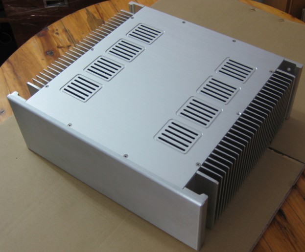
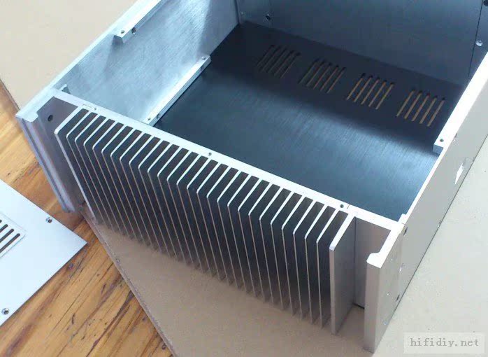
does this chassis/heatsink seem enough for 2x175w dissipation?
heatsink size 300x150 each side
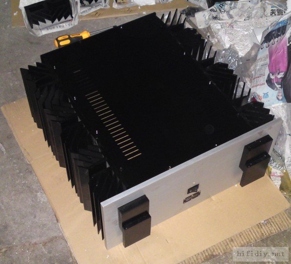
or would it need something as extreme as
I can't get thermal specs on either of these chassis,
but the price is pretty reasonable.
If i build this as a stereo chassis, it's perfect if i decide to go balanced, I can convert each stereo amp into a balanced monoblock.
with the amps bridged/balanced they will effectively see 1/2 the speaker impedance so the higher bias /stock voltage seems to fit well?
does this chassis/heatsink seem enough for 2x175w dissipation?
An externally hosted image should be here but it was not working when we last tested it.
heatsink size 300x150 each side
An externally hosted image should be here but it was not working when we last tested it.
or would it need something as extreme as
An externally hosted image should be here but it was not working when we last tested it.
I can't get thermal specs on either of these chassis,
but the price is pretty reasonable.
- Status
- This old topic is closed. If you want to reopen this topic, contact a moderator using the "Report Post" button.
- Home
- Amplifiers
- Pass Labs
- F5 Turbo V1, modified for more Class A power into 4 ohms