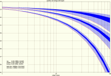
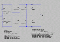
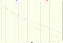
Being interested in how different transformer sizes might affect amplifier performance, I did some simulations in LTspice. I was mainly looking for the difference in secondary wire gauge and the resulting output resistance. Thus such things as regulation or saturation are not considered here, simply the different secondary copper resistances as stated in the datasheets were used. The load is steady and purely resistive. Output power calculation is already taking into account the typical 67% efficiency of a class AB amplifier.
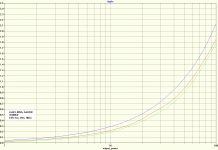
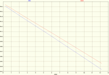
The second chart shows the influence of the filter cap's ESR, like 49mR for a single one or 4mR for 10 smaller ones in parallel.
This is actually pretty basic stuff, nonetheless it's quite interesting to look at...
The second chart shows the influence of the filter cap's ESR, like 49mR for a single one or 4mR for 10 smaller ones in parallel.
This is actually pretty basic stuff, nonetheless it's quite interesting to look at...
Attachments
Hey this is very interesting stuff, and closely related to another thread that has been going on in this forum:
http://www.diyaudio.com/forums/power-supplies/216409-power-supply-resevoir-size.html
I recently developed an Excel spreadsheet to model this kind of power supply, connected to a class-AB amplifier that is driving a resistive load. Here is a link to the spreadsheet:
http://audio.claub.net/software/PS_dimensioning/Power_Supply_capability_calculations_VER2.2.xls
There are similarities with your results, but I did not include ESR of the caps.
I would like to expand the spreadsheet to include CRC type capacitor banks, and include the cap ESR, but it would need to be done with equations instead of simulation. Would this be straightforward to formulate into an equation? Could our results be combined?
-Charlie
Are you using Rser to model secondary resistance?
Then a range from 0r06 to 0r85 covers an enormous range of VA in transformers. I'd guess from 2kVA to 100VA.
Hardly what one would select as a possible range of usable transformers for a specific power amplifier.
I think your Rload is too simple. The amplifier actually draws a half sinusoid in each power rail, when delivering significant power to the amplifier load, assuming of course that Iq has become small in comparison. This may throw up some differences in the way the model predicts actual behaviour.
I also suspect the Rser is too simple for what you're modeling.
Last edited:
Charlie, your spreadsheet doesn't work for me since I only have OpenOffice  .
.
ESR doesn't make that much of a difference, unless it's much too high. But since Low-ESR caps are common these days, that should not be a problem.
Andrew,
yes, I used Rser, as can be seen from the schematic.
The VA range is actually 80, 160 and 500 for each transformer with its two secondaries. The data is taken from actual datasheets.
I have a big toroid lying around with 3x24V @ 9A each and I'm considering to use it for something like a P3A or MyRef, which could easily be built with 160VA for 'home use'. Granted, 80VA is too weak, but for smaller amps you might consider to double that up to 160VA...
Of course this is only a simple simulation, leaving out the intrinsic behaviour of the toroid itself, which should make things even worse. I stated that above. But nonetheless does the difference in secondary winding resistance make a difference in output voltage under load, which is shown here.
I did not quite get what you mean here. A real amplifier will behave different than a resistor, that's for sure, but a constant resistive load should be something like the worst case. The amplifier load on the psu will vary depending on the music signal, even into a purely resistive load (think of white noise vs. 50Hz sinus). In the simulation the load is constant.
ESR doesn't make that much of a difference, unless it's much too high. But since Low-ESR caps are common these days, that should not be a problem.
Andrew,
yes, I used Rser, as can be seen from the schematic.
The VA range is actually 80, 160 and 500 for each transformer with its two secondaries. The data is taken from actual datasheets.
I have a big toroid lying around with 3x24V @ 9A each and I'm considering to use it for something like a P3A or MyRef, which could easily be built with 160VA for 'home use'. Granted, 80VA is too weak, but for smaller amps you might consider to double that up to 160VA...
Of course this is only a simple simulation, leaving out the intrinsic behaviour of the toroid itself, which should make things even worse. I stated that above. But nonetheless does the difference in secondary winding resistance make a difference in output voltage under load, which is shown here.
I think your Rload is too simple. The amplifier actually draws a half sinusoid in each power rail, when delivering significant power to the amplifier load, assuming of course that Iq has become small in comparison. This may throw up some differences in the way the model predicts actual behaviour.
I did not quite get what you mean here. A real amplifier will behave different than a resistor, that's for sure, but a constant resistive load should be something like the worst case. The amplifier load on the psu will vary depending on the music signal, even into a purely resistive load (think of white noise vs. 50Hz sinus). In the simulation the load is constant.
Too simplified in my opinion.
Losses are proportional to I^2R and a constant current Rload underestimates this significantly.
0r06 is in the sim
0r08 is still too low for a 500VA
I measured 0r09 for a 1kVA transformer recently. I have never measured as low as 0r06 in any of my secondaries.
Losses are proportional to I^2R and a constant current Rload underestimates this significantly.
0r06 is in the sim
0r08 is still too low for a 500VA
I measured 0r09 for a 1kVA transformer recently. I have never measured as low as 0r06 in any of my secondaries.
Last edited:
Charlie, your spreadsheet doesn't work for me since I only have OpenOffice
Uh, did you even try it? I can open it just fine with OO 3.3 Calc...
The only thing I saw that was not right was the labels in the plots.
-Charlie
Losses are proportional to I^2R and a constant current Rload underestimates this significantly.
What kind of losses? And why should the constant current underestimate this? What kind of load should I use instead?
0r06 is in the sim
0r08 is still too low for a 500VA
I measured 0r09 for a 1kVA transformer recently. I have never measured as low as 0r06 in any of my secondaries.
I attached the datasheet. I do not own such a trafo so I can't prove if that's true.
Uh, did you even try it? I can open it just fine with OO 3.3 Calc...
Yes, I did. With Calc 3.4. I cannot see any output, changing the input fields doesn't do anything.
Attachments
Yes, I did. With Calc 3.4. I cannot see any output, changing the input fields doesn't do anything.
You had me worried for a moment, so I just updated to 3.4.1 and re-opened the same xls file and... it works just like in version 3.3... So, I am not sure what problem you are experiencing.
I can change all of the input fields and see all the output plots change as a result...
When did you last update your OO version?
-Charlie
Rather a simple model for the transformer, use a transformer equivalent circuit and plug in the appropriate values. Impedance from leakage inductance is usually of the same order as the DC resistance. Measure a real transformer, apply a DC current to the secondary and measure the voltage developed across it. Use a multimeter on the primary, unless it is a large transformer otherwise use the technique mentioned. Power up the transformer, measure the input and output voltage, apply a resistive load then measure the load current and voltage. The voltage sag / load current will give the transformer output impedance.
The leakage inductance can be inferred by subtracting the output referred resistance from the output impedance. This is a vector subtraction.
To calculate the output referred resistance, divide the primary DC resistance by the square of the turns ratio and add this to the secondary DC resistance.
As for the load current, it will rarely be worse than a half sinusoid of vcc -5V across either a 6 or 3 ohm load depending on the use of 8 or 4 ohm speakers. I am too tired to derive the maths for this, any power supply design reference will cover half wave supplies, a half wave load uses the same equations.
nothing beats actual live testing...the built up amp with the psu, a dummy load and signal source and testing for voltage droop at full power....
in my 250wpc super leach, unloaded rails are +/-85volts...both channels putting out 45vac, the dc rails drop to about +-75volts....
the EI power traffo used a 2inch center leg stacked to 3.5inches for a core rating of roughly 1500voltamperes....
in my 250wpc super leach, unloaded rails are +/-85volts...both channels putting out 45vac, the dc rails drop to about +-75volts....
the EI power traffo used a 2inch center leg stacked to 3.5inches for a core rating of roughly 1500voltamperes....
Seems like others have already bent their heads around this topic: Anyone have SPICE models for PSU Toroidal Xfmr ??.
Actually I find this to be a bit too elaborate, because it involves measuring on actual transformers. I was looking for a quicker way, not having to order and measure each possible transformer. I will run the same simulation with the model found in the linked thread and make a comparison, though, to see how big the difference is.
Charlie,
now everything works fine! Somehow the tabs for selecting the different sheets got lost and I didn't even consider there might be some more, so I didn't notice it in the first place...
Here are the comparison charts. I used the simulation model from Tom Gootee with the measured data of my trafo.
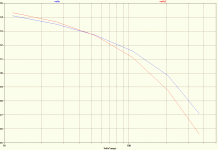
The first chart shows both models with a simple resistive load on the ac, where the blue line resembles Tom's model and the red line my simple approach.
On the other charts the models were loaded with a full bridge rectifier, 4700uF (ESR=63m) and the stepped resistor. Same colour coding here.
Unfortunately I don't have a transformer with lower VA and equal voltage rating at hand. This would have made the comparison much more descriptive.
Please note that these comparison charts took more than half an hour to simulate, while the simple model is only a matter of seconds .
.
The first chart shows both models with a simple resistive load on the ac, where the blue line resembles Tom's model and the red line my simple approach.
On the other charts the models were loaded with a full bridge rectifier, 4700uF (ESR=63m) and the stepped resistor. Same colour coding here.
Unfortunately I don't have a transformer with lower VA and equal voltage rating at hand. This would have made the comparison much more descriptive.
Please note that these comparison charts took more than half an hour to simulate, while the simple model is only a matter of seconds
Attachments
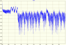
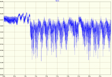
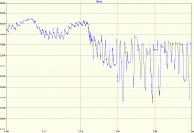
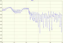
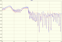
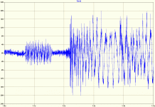
Made a more comprehensive simulation. This time I used the complete P3A circuit with a 2 Ohm resistive load and an actual wave file as input source. The power supply consists of a single rectifier bridge for both rails, 10.000uf of capacitance for each rail, and two modeled transformers.
Simulation time was almost four hours versus a quarter; the generated raw files grew to a full 36GB and 1GB, respectively.
#1: Elaborate Model, 5 seconds of music into 2 Ohms, positive voltage rail shown
#2: Simple Model, 5 seconds of music into 2 Ohms, positive voltage rail shown
#3: Elaborate Model, section of 0.5 seconds for better resolution
#4: Simple Model, section of 0.5 seconds for better resolution
#5: Overlay of both models for direct comparison, Simple one shown in red
#6: amplifier output voltage
Attachments
Last edited:
It could be useful if flux density could be included, for which the number of turns and core area would be required. To my mind, it is important for an audio ps transformer to remain in the linear region of the BH curve, to minimise the generation of harmonics. For this reason, a transformer should be operated at its rated power. In practice, there isn't much choice: buy what a reputable manufacturer has made for your power requirement and purpose. Don't buy a higher-powered transformer just for the sake of lower winding resistance.
For the ohm's law view of the consequences of your choice, psud is good:
PSUD2
from a truly great pioneer of internet DIY audio.
For the ohm's law view of the consequences of your choice, psud is good:
PSUD2
from a truly great pioneer of internet DIY audio.
For this reason, a transformer should be operated at its rated power.
The datasheets I have looked at state that the transformer ratings are calculated for a temperature rise of 50 degree centigrade, which is not desirable IMO. Moreover the load of a typical class AB amp playing typical music is everything else but constant and you don't always run your amp on full power output, so the transformer won't be operating at its rated current most of the time.
It could be useful if flux density could be included, for which the number of turns and core area would be required. To my mind, it is important for an audio ps transformer to remain in the linear region of the BH curve, to minimise the generation of harmonics. For this reason, a transformer should be operated at its rated power. In practice, there isn't much choice: buy what a reputable manufacturer has made for your power requirement and purpose. Don't buy a higher-powered transformer just for the sake of lower winding resistance.
For the ohm's law view of the consequences of your choice, psud is good:
PSUD2
from a truly great pioneer of internet DIY audio.
+1.... "Don't buy a higher-powered transformer just for the sake of lower winding resistance." commercial transformers operate at higher flux densities so that less copper is used...if you go diy route and build your own transformers you are not constrained by this consideration, i do my traffos at less than 1T most of the time, some are in the 0.6T levels....
+1.... "Don't buy a higher-powered transformer just for the sake of lower winding resistance." commercial transformers operate at higher flux densities so that less copper is used...if you go diy route and build your own transformers you are not constrained by this consideration, i do my traffos at less than 1T most of the time, some are in the 0.6T levels....
Absolutely the way to go if you can do it and have the time. Most of my experience is with valves, for which it's normal to use transformers made with audio in mind, and plenty are available. For low-voltage audio, choice and availability seems more limited, perhaps because commodity-grade items are so common and cheap. Since I have only just stumbled into the 1980s, perhaps I haven't found the good stuff yet.
This wasn't the best place to raise my gripe, perhaps. It appears common in low-voltage DIY audio to use bigger transformers than necessary. Presumably this is in an effort to reduce sag during loud bits. Although this may be true, if it is done just by over-specifying a commodity-grade transformer, the chances are it will be noisy exactly when it needs to be quietest...during the quiet bits.
Perhaps everyone uses shunt regulation?
The datasheets I have looked at state that the transformer ratings are calculated for a temperature rise of 50 degree centigrade, which is not desirable IMO. Moreover the load of a typical class AB amp playing typical music is everything else but constant and you don't always run your amp on full power output, so the transformer won't be operating at its rated current most of the time.
I did go on to say that it should be rated for the intended purpose. Power is by nature an average, and transformers are slow to heat, so the average can be over a long time. Hence a class AB amp won't need as big a transformer as class A. Choosing the rating is quite problematic though. If I used a commodity transformer I would consider shunt regulation, and a chimney.
Properly-specified commodity-grade transformers may well run hot, but over-specifying may result in a significant increase in electrical and mechanical noise. For most transformers, regulation via winding resistance is a necessary evil, because rated current drops the voltage across the magnetising inductance sufficiently to operate the core in its linear region.
A transformer specifically wound for audio should minimise this compromise, and several others.
I didn't mean to devalue your efforts, but rather suggest a way to make them more useful. For simulation, I made a model with a flux density output, which turned out to be quite an eye-opener.
Choosing the rating is quite problematic though. If I used a commodity transformer I would consider shunt regulation, and a chimney.
I'd like to keep the trafo as cool as possible instead...
Properly-specified commodity-grade transformers may well run hot, but over-specifying may result in a significant increase in electrical and mechanical noise.
Could you specify this a bit more for me, please? I'm not that deep into transformers yet, but I guess there's no way around
Mechanical noise should be no concern IMHO, since I haven't seen any toroidal transformer producing any, regardless of the load conditions. Don't know anything about the electrical noise you mentioned, though.
I didn't mean to devalue your efforts, but rather suggest a way to make them more useful. For simulation, I made a model with a flux density output, which turned out to be quite an eye-opener.
Since I'm not going to wind my own transformers, there seems to be no point in further doing any simulations, I guess?
I'd like to keep the trafo as cool as possible instead...
Could you specify this a bit more for me, please? I'm not that deep into transformers yet, but I guess there's no way around.
Mechanical noise should be no concern IMHO, since I haven't seen any toroidal transformer producing any, regardless of the load conditions. Don't know anything about the electrical noise you mentioned, though.
Since I'm not going to wind my own transformers, there seems to be no point in further doing any simulations, I guess?
Not on my account, please. I was rather hoping you'd try including flux density. The maths is easy, up to a point, which is where I got stuck. I can model on the basis of constant inductance, and simulate the core flux. That allows me to know when the transformer would be distorting, but not to quantify the distortion. For that I need to calculate the change in inductance and feed the result back into the model. The problem is finding a way to model the BH curve of iron in SPICE.
It would be daft to value what you have by what you haven't.
The most useful thing, perhaps, would be to compare two transformers, in reality and by calculation. You seem close to being able to do that, with the same music
It may well be that, up to a point, the effects you have shown will dominate the picture.
When I use music in my spice, I get noise and distortion from a straight piece of wire
- Status
- This old topic is closed. If you want to reopen this topic, contact a moderator using the "Report Post" button.
- Home
- Amplifiers
- Power Supplies
- Transformer voltage droop
