So I have a classic beetle ('69) and the owner put in an old Sapphire XI back in it after a previous previous owner had an aftermarket deck in it. Well after a bit of bench testing I've determined the only thing that works is the light in the front. lol As much as I would love spending time and money diagnosing an AM radio I decided to clean the case out and attempt to build a small amp to replace it.
The amp:
Needs to take the output of a phone or MP3 player and amp it up to drive a single 4" speaker (5w currently). I know boring right? In the future I may consider something with more kick but nothing audacious. I hate aftermarket audio equipment in Beetles. There's a reason I'm even bothering with converting this deck.
The chip(s):
Pretty sure these aren't audiophile's choice but they are cheap at my work and fit my voltage requirements. I have at most 14v in the system with the amp running but can only trust 12v of that. I have a pair of NTE740A. Spec sheet:
http://www.nteinc.com/specs/700to799/pdf/nte740a.pdf
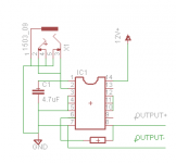
What I can gather about how this thing is supposed to be used coalesced into an eagle diagram:
It doesn't have the pot on there. Ideally I will use a chip per channel and combine their outputs to the single speaker but not sure on that idea and I think one can drive the 8ohm 5w speaker (quietly) for prototyping so I drew it up that way.
Critiques or Comments?
The amp:
Needs to take the output of a phone or MP3 player and amp it up to drive a single 4" speaker (5w currently). I know boring right? In the future I may consider something with more kick but nothing audacious. I hate aftermarket audio equipment in Beetles. There's a reason I'm even bothering with converting this deck.
The chip(s):
Pretty sure these aren't audiophile's choice but they are cheap at my work and fit my voltage requirements. I have at most 14v in the system with the amp running but can only trust 12v of that. I have a pair of NTE740A. Spec sheet:
http://www.nteinc.com/specs/700to799/pdf/nte740a.pdf
What I can gather about how this thing is supposed to be used coalesced into an eagle diagram:
It doesn't have the pot on there. Ideally I will use a chip per channel and combine their outputs to the single speaker but not sure on that idea and I think one can drive the 8ohm 5w speaker (quietly) for prototyping so I drew it up that way.
Critiques or Comments?
Attachments
Last edited:
Update:
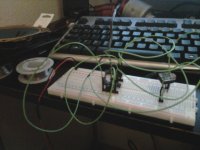
I quickly threw together a breadboard and the little chip sung me a song... very quietly almost indistinguishable from random static. So I continued by trying to hook up the second chip in hopes it would double the volume (or better if you consider that whole logarithmic hearing business). Well I hooked back up the power once I was done and my audio was no longer audible, not a peep. I unhooked the second chip and my audio came back. Grabbed a second end to my wall adaptor and plugged it in and the audio became loud enough to make out words, still strained though. Plug in the second chip again and the audio disappeared.
This all sounds like my power adaptor is not stout enough (12v 1A). Wanted to see what the community said before I rig up a test stand with a bit more oomph.
Attachments
If I'm understanding correctly... you don't want to combine the channels at the output of the amplifiers. You want to combine the channels and send them to the amp input. That NTE part is a substitution-type device; I'll have to check what the generic part number is to put myself in a better position to comment further.
edit1: Your chipamp is an LM380 equivalent. Do a web search for "LM380 bridged" and if you don't find anything (doubtful) I'm sure I have a circuit around here. There may well be one in the LM380 datasheet.
edit2: Download the Texas Instruments (National Semiconductor) LM380 datasheet and also LM380 application note AN-69. The very simple bridge circuit is shown in each.
The 2-to-1 channel summing circuit can be found here in the forums, active or passive.
Last edited:
"Needs to take the output of a phone or MP3 player and amp it up to drive a single 4" speaker (5w currently). I know boring right?"
You know what? it is NOT boring. And honestly, at least You figured out a reasonable challange.
I highly respect that.
Prehaps You might want to give a try with a more powerfull chipamp.
Tda 1557 q might be more suited, and is around the same challange to build it.
You know what? it is NOT boring. And honestly, at least You figured out a reasonable challange.
I highly respect that.
Prehaps You might want to give a try with a more powerfull chipamp.
Tda 1557 q might be more suited, and is around the same challange to build it.
I can't find a supplier I trust for that TDA. Mouser has some TB2946HQ. Besides being quadraphonic and having a little more oomph it looks pretty similar.
The thing that worries me is the rating is for a 4ohm speaker (test speaker is 8ohm). Now if I can figure this right in my head W=VA A=V/I W=V(V/I) Which shows me as the ohm of the speaker increases the overall wattage supplied to it decreases. Think it will still drive it? The tester speaker is only rated at 5W after all.
Also one thing I don't get. I think I can pull 8-9W@12Vcc on a 4ohm speaker which in cars average 90DB/W@1m. Is it right to say that speaker can put out 810DB@1M? That's astronomically loud.
Update:
I now know how sensitivity works so ignore that last question. lol
SO I got distracted by a project that is a little more... digital about it's power requirements. The wall adapter I was working with turned out to do terrible work powering anything. So I did a little personal affects searching and found an old computer power supply. A bit of a jump start and the clean 12V provided by a floppy plug powered the new toy perfectly. So I began to wonder about this project.
I hooked everything up and this time I didn't have to hug my ear to the coil to hear a noise but it was still pretty quiet. I began fiddling with wires and thought "Hey I'll shut it off by removing the ground from the PSU." Instead of dying it got MUCH louder for a second or two and then real quiet. Grounding through the headphone jack on my desk speakers? Fiddled with it for awhile longer doing this loud/quiet act until it stopped responding to my fiddling and just went silent. What's up with this grounding scheme and why does it go quiet like that?
I think I left that pin open this last run. I'll ground it. Makes the left side of the chip pretty simple.
"run the amp into clipping which can send DC to the speaker"
Found this in my search for discussions on output caps. This may have been part of my issue... I know I drove it to clipping at least once due to the the silliness of the crazy non-linearity (may I say snap response) of my speaker's headphone output. So I'll work on that selection and implement it. I shot the speaker's coil after it went quiet and got (effectively) 8ohm so it's fine.
Last edited:
The output cap doesn't protect the speaker from clipping.
With a single-supply amp, the output is biased at half the supply voltage. An output capacitor will block this continuous DC flow through the speaker.
When an amp clips, the wave top is chopped off (clipped) and that DC will flow through the speaker.
With a single-supply amp, the output is biased at half the supply voltage. An output capacitor will block this continuous DC flow through the speaker.
When an amp clips, the wave top is chopped off (clipped) and that DC will flow through the speaker.
Depends on the part. I've been cobbling together the ideas I can find on every subject.
Speaker coupling cap:
ecp audio diy: Some Notes on Coupling Capacitors
Wasn't real sure on this one...
The bypass cap is a bit of a personal decision derived from Figure 5 of AN-69.
Vs coupling cap too comes from AN-69:
"The normal power supply decoupling precautions should be taken when installing the LM380. If VS is more than 2" to 3" from the power supply filter capacitor it should be decoupled with a 0.1 mF disc ceramic capacitor at the VS terminal of the IC."
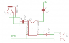
As far as C1 is concerned as soon as I started to type "I've been scouring the web..." I thought up something new to search and it turned up electrical diagrams of LM380s being used many with C1 as a shunt... something AN-69 failed to example as I was making this diagram. Which I now feel silly because even wikipedia knew C1 was supposed to be shunt upon further inspection.
Speaker coupling cap:
ecp audio diy: Some Notes on Coupling Capacitors
Wasn't real sure on this one...
The bypass cap is a bit of a personal decision derived from Figure 5 of AN-69.
Vs coupling cap too comes from AN-69:
"The normal power supply decoupling precautions should be taken when installing the LM380. If VS is more than 2" to 3" from the power supply filter capacitor it should be decoupled with a 0.1 mF disc ceramic capacitor at the VS terminal of the IC."
As far as C1 is concerned as soon as I started to type "I've been scouring the web..." I thought up something new to search and it turned up electrical diagrams of LM380s being used many with C1 as a shunt... something AN-69 failed to example as I was making this diagram. Which I now feel silly because even wikipedia knew C1 was supposed to be shunt upon further inspection.
Last edited:
You're learning so don't feel bad.
I took a quick look at the coupling cap link and the formula for the output coupling is there: F = 1/(2 * pi * C * R). The form needs to be changed, though, to C = 1/(2 * pi * F * R) to solve for the unknown cap value C. And you'll need to determine the frequency (F in the formula) -3dB lower cutoff point for your circuit. R is the speaker impedance. So C3 is much too small; it needs to be at least 100 times bigger.
edit: Figure 5 in AN-69 is the power bandwidth of the chip amp. It gives insight to the internal workings of the IC. I look at it as another spec of the amplifier; it doesn't really help with determining bypass or coupling cap values.
Last edited:
C1 should not be in series with the power supply, but in parallel.
C3 should be between several hundred and a few thousand µF. The link you posted relates to preamplifiers that are loaded with kOhms. Most speakers have 4-8 Ohms and with only 4,7 µF you will not hear anything below 4-8 kHz.
C3 should be between several hundred and a few thousand µF. The link you posted relates to preamplifiers that are loaded with kOhms. Most speakers have 4-8 Ohms and with only 4,7 µF you will not hear anything below 4-8 kHz.
Not too much. You are not building a high end system with that IC.He has a warning that the cap will cause distortion up to 10x the corner frequency. How much should I worry about that?
Sounds resonable.If not much then size considerations would drive me towards a 470uF.
- Status
- This old topic is closed. If you want to reopen this topic, contact a moderator using the "Report Post" button.
- Home
- Amplifiers
- Chip Amps
- Amp newbie attempting project