Dear diy'ers,
attached you can find my diy version of a very good and warm sounding 4 channel gainclone based on LM4562 and 2 x LM3886.
Feel free to re-use my schematics and pcb for DIY!
To manage mains there is a pic microcontroller based control circuit.
Best regards,
Toni


View attachment lm3886_inv_btl_schematics_and_pcb.zip
attached you can find my diy version of a very good and warm sounding 4 channel gainclone based on LM4562 and 2 x LM3886.
Feel free to re-use my schematics and pcb for DIY!
To manage mains there is a pic microcontroller based control circuit.
Best regards,
Toni
View attachment lm3886_inv_btl_schematics_and_pcb.zip
Last edited:


I'm not allowed to put in the word I am thinking !!!
I had a post written and clicked on a pic. The Forum downloaded a revised page with the pic. When I returned to where I was, my post was lost.
Why does the Forum sometimes on clicking superimpose the pic alongside where one currently is and at other times take one to a new page?
I had a post written and clicked on a pic. The Forum downloaded a revised page with the pic. When I returned to where I was, my post was lost.
Why does the Forum sometimes on clicking superimpose the pic alongside where one currently is and at other times take one to a new page?
Last edited:
How about adding a note that the decoupling caps Cs are located on the amp PCBs and not as shown on the PSU schematic.
How does output offset vary with time from start up and/or with temperature?
Can you include details of the MCU operation and how we can duplicate that functionality?
Why does the FFT show both 50Hz and 60Hz and the harmonics of both?
And congrats on the super drawings.
Clever use of the sawn in half heatsink to fit all 4 amplifiers inside your chassis and still give adequate cooling. Nice.
I have a similar sink but it's only 50mm tall. If instead of having 12 @ 50mm I had 6 @ 100mm high I would never have any cooling problems. What height is your extrusion?
Last edited:
How about adding a note that the decoupling caps Cs are located on the amp PCBs and not as shown on the PSU schematic.
How does output offset vary with time from start up and/or with temperature?
Can you include details of the MCU operational and how we can duplicate that functionality?
Why does the FFT show both 50Hz and 50Hz and the harmonics of both?
And congrats on the super drawings.
Many questions in one post ...
1) The "PSU" that you mean are the bypass capacitors already located on the amplifier pcb. As we have here 2 types of GND (power GND and analog GND) I have decided to draw this an the amp circuit.
2) I have built 4 amplifiers and the output DC offset varies from 1mV to 35 mV. As the amp warms up the DC offset is getting lower. The DC offset depends mainly on the LM4562 input stage. If one would match/check the used input opamps, there would be nearly no DC offset as the two LM3886 are galvanically coupled to the input/inverter stage.
3) Maybe someday you will find the firmware and C source-code using SDCC compiler to self edit the firmware. As the "mains inrush controller" is not directly needed for this project, I will open a new thread if there is enough interest on it.
What is controlled by the MCU/inrush controller (which itself is always powered by a small PSU):
- Controls the 2 mains relays to suppress inrush current. Supports two high power toroids. Timing is configurable. (typically 250ms delay)
- mute signal during power on/off.
- power on/off button (on switch or push button with power state saving in eeprom)
- external power on/off (e.g.: needs additional optocoupler)
- 3 configurable temperature sensors (e.g.: left/right heatsink; case temperature)
- DC speaker controll - emergency power off - locked
- RS232-TTL-Level-Interface for configuration only or for connection to another MCU (e.g.: to support IR remote control, Voltage sensors etc.)
Thank you,
Toni
Clever use of the sawn in half heatsink to fit all 4 amplifiers inside your chassis and still give adequate cooling. Nice.
I have a similar sink but it's only 50mm tall. If instead of having 12 @ 50mm I had 6 @ 100mm high I would never have any cooling problems. What height is your extrusion?
Dear AndrewT,
sorry I have overseen your last question:
The heat sink model: KS216-100E (0.4 K/W) before "saw in action". Size: 216x83x100mm.
An LR24 stateful variable active crossover divides the signal before amp input into bass and mid/treble (crossover point 400Hz). So the heat sinks are big enough as only 2 amplifiers are providing high power.
Regards,
Toni
I like this method of design and is the way I have been planing driving my chipamp design for a BTL configuration.
Thanks for posting the THD graphs.
Cheers!!!
jer")
Dear jer,
you mean you already have a similar design ...
Regards, Toni

Why does the FFT show both 50Hz and 60Hz and the harmonics of both?
Dear AndrewT,
about the 50 Hz: our mains is running 50Hz. I thought about the 60Hz artefacts and the only source with 60Hz:
The connected LCD monitor get it's video signal with 60Hz refresh ... could it be the video card generating a sharp 60 Hz pulse?
Regards, Toni
I have used that input phase splitting input configurations for many years in simulations and a few projects.
I have been wanting to try it driving some LM4870's that I have five of for a BPA400 or 800 setup or something.
As I was going to get some more when National Semiconductor used to send you some free samples .
I haven't messed with them because I recently got my big power amps back from Florida.
Now I find my requirements are more for a parallel style setup for my ESL's.
But here is the start of my project,
http://www.diyaudio.com/forums/chip-amps/190936-tda7293-bridge-parallel-circuit.html#post2608127
I wanted to not have to use a transformer or any special opamps.
When I first started using the circuit in the 90's, differential output opamps were scarce and a bit rare to find.
I also used the same method for this bass preamp for a fellow DIYer,
http://www.diyaudio.com/forums/inst...ed-direct-output-di-bass-amp.html#post2883491
Cheers!!
jer
Last edited:
dear jer,
interesting variant of the inverter stage. Are you sure you are not worsening johnson noise and/or stability? With LM4562 the inverter stage alone works better as my lab equipment can measure. Also 180 degree phase shift is exactly reproduced on my 150MHz OSC ...
Regards, Toni
interesting variant of the inverter stage. Are you sure you are not worsening johnson noise and/or stability? With LM4562 the inverter stage alone works better as my lab equipment can measure. Also 180 degree phase shift is exactly reproduced on my 150MHz OSC ...
Regards, Toni
I don't know if it increases any noise.
I do know that the same technique is used to increase the CMRR of a balanced inputs to a preamp stage or a line stage.
I got the idea out of one of Walter Jung's books on opamp applications.
My thought is that it might help keep the propagation delay equal on the two outputs compared to the input signal.
There was a study started a while back in a thread about which has less THD, a Paralleled amp or a Bridged amp.
The TDA7293 was used.
I can find the link if you like.
jer
Last edited:
Here is the link with some interesting results,
http://www.diyaudio.com/forums/chip-amps/197398-tda7293-single-bridge-parallel.html#post2725581
Jer
http://www.diyaudio.com/forums/chip-amps/197398-tda7293-single-bridge-parallel.html#post2725581
Jer
Dear AndrewT,
this is to be compared. See schematic.
Left: high input impedance
Right: needs low input impedance. Input will be attenuated to 50%.
The Question is: does the right variant help to keep the propagation delay equal on the two outputs compared to the input signal?
Regards, Toni
this is to be compared. See schematic.
Left: high input impedance
Right: needs low input impedance. Input will be attenuated to 50%.
The Question is: does the right variant help to keep the propagation delay equal on the two outputs compared to the input signal?
Regards, Toni
Attachments
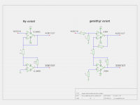
the 1k+1k (-6dB) attenuator on the input has absolutely no influence on the propagation delay of the single ended to differential stage.
It simply changes the sensitivity of the whole stage by 6dB. i.e. the My variant needs less input for the same output, if the stage gains are the same.
I'm not so sure about the effects that the changed feedback network have.
The gain of both parts of My are set to 1 (+0dB).
It simply changes the sensitivity of the whole stage by 6dB. i.e. the My variant needs less input for the same output, if the stage gains are the same.
I'm not so sure about the effects that the changed feedback network have.
The gain of both parts of My are set to 1 (+0dB).
Last edited:
Here are a few things,
http://waltjung.org/PDFs/ADI_1993_Seminar_Audio_Drivers.pdf
http://waltjung.org/PDFs/Op_Amps_in_Line_Driver_and_Receiver_Circuits_P2.pdf
On page 42 of this document is pretty much what was in my book and page 69 is something similar as well but more involved as it is a diagram of a SSM2142 driver chip,Page 113 and 138 is of interest of the cross coupled driver in more detail,page 161 is more like the configuration I came up with only it has a balanced input configuration,
http://www.analog.com/library/analogDialogue/archives/39-05/Web_Ch6_final_I.pdf
I don't know off hand were my book is as it is in a few pieces as I have read it so much through the years.
But if I can locate it soon I will scan the pages in it as well and post them.
Here is were I found these links,
Services
Great stuff !!!
jer
Last edited:
- Status
- This old topic is closed. If you want to reopen this topic, contact a moderator using the "Report Post" button.
- Home
- Amplifiers
- Chip Amps
- LM3886 running inverting only and bridged - for 8 Ohms only