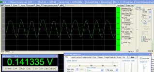
Hello, I am using Visual Analyser with a mic as input. When picking up a 7kHz sine wave from a nearby speaker the following is observed:

Lower frequencies, 500-1000 are not as distorted.
On the frequency response graph, there is also a lower frequency spike that sort of follows the higher one, and is of considerable amplitude:

I was wondering if anyone could suggest any causes.
The soundcard is not of a high quality, and the processor is a single core, 1.8 GHz. The speakers are a 3" and a 1" tweeter for the higher frequencies, which sound very clear and undistorted.
The mic is homemade, but the same results are obtained with a known-good,commercial desktop mic.
Also, the testing is done in a highly reflective room, in a part of it that is less than 17 feet at the longest, if these are any help.

Lower frequencies, 500-1000 are not as distorted.
On the frequency response graph, there is also a lower frequency spike that sort of follows the higher one, and is of considerable amplitude:

I was wondering if anyone could suggest any causes.
The soundcard is not of a high quality, and the processor is a single core, 1.8 GHz. The speakers are a 3" and a 1" tweeter for the higher frequencies, which sound very clear and undistorted.
The mic is homemade, but the same results are obtained with a known-good,commercial desktop mic.
Also, the testing is done in a highly reflective room, in a part of it that is less than 17 feet at the longest, if these are any help.
Last edited:
Thanks guys. That is the spot. The FFT Size also plays a part as well, having tried a few combinations. D/A does nothing.
The extra, lower spikes are still there for most frequencies, however, especially the one that divides by around 4.7. I was hoping to only see the fundamental and a few harmonics afterward.
Does anyone have a "best bet" on improving from here?
The sound card is rubbish, the preamp circuit is unshielded, and lacks any filtering, except for bypass caps on the amp rails.
The power supply is Ni-Cd with a laptop charger keeping the voltage constant. In fact, a slight amount of noise increase is noticed when the charger is removed.
Looks like its drawing straight lines between sample points. Which is what its supposed to do. (unless you want the software to fill in the gaps with guesses, which it should be able to do accurately for a sine wave, but if you start using it for music, not so good.) You need a sample rate 10x the highest freq. to be accurate. or 70k in your case.
Looks like its drawing straight lines between sample points. Which is what its supposed to do. (unless you want the software to fill in the gaps with guesses, which it should be able to do accurately for a sine wave, but if you start using it for music, not so good.) You need a sample rate 10x the highest freq. to be accurate. or 70k in your case.
Actually the oscilloscope function has a mode called true D/A mode in which it should be using an ideal reconstruction filter. That should restore any waveform that has no frequency components at or above half the sample rate. That's why I'm surprised that the D/A button does nothing.
ITPhoenix, how far are the remaining spikes below the desired signal? In your original plot, the f/4.7 component is some 66 dB below the desired. That could be due to interference from the computer on your preamplifier, or from soft background sounds, although one would not expect any relation with the frequency of the desired signal then. What does the spectrum look like when you replace the microphone with a resistor having roughly the same impedance, or when you insert the 7 kHz electrically into your preamp using a resistive voltage divider?
Looks like its drawing straight lines between sample points. Which is what its supposed to do. (unless you want the software to fill in the gaps with guesses, which it should be able to do accurately for a sine wave, but if you start using it for music, not so good.) You need a sample rate 10x the highest freq. to be accurate. or 70k in your case.
What I see on Audition for waveforms is extremely close to what I see on my Tek scope. They (Audition) do not fill in the gaps with 'guesses'.
I never tried Visual Analyzer but that display in post one is totally useless and gives no hint as to what may be really happening.
G²
Actually the oscilloscope function has a mode called true D/A mode in which it should be using an ideal reconstruction filter. That should restore any waveform that has no frequency components at or above half the sample rate. That's why I'm surprised that the D/A button does nothing.
ITPhoenix, how far are the remaining spikes below the desired signal? In your original plot, the f/4.7 component is some 66 dB below the desired. That could be due to interference from the computer on your preamplifier, or from soft background sounds, although one would not expect any relation with the frequency of the desired signal then. What does the spectrum look like when you replace the microphone with a resistor having roughly the same impedance, or when you insert the 7 kHz electrically into your preamp using a resistive voltage divider?
There is substantialimprovement using the tone generator. The spikes below come and go depending on frequency. The one that is close to the desired is only 26 dB lower, while another farther behind is a little less than that. Keep in mind the response graph is set to log with the Y axis adjusted to show almost everything. If log is unticked, only the set frequency shows up with some insignificant noise at the bottom.
The gradual ramp from 0 to 20Hz, with the big dive thereafter, is the DC component of the sound card, around 2.8mV (the level of "no input" noise), or it is in the software, the 5% accuracy of the calibration voltage, or some combo of all three.
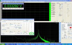
Here is what log looks like with nothing plugged into the input:

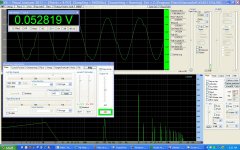
Now with a clean input at what could be called a crossover point:

The following is 1980 Hz clean:

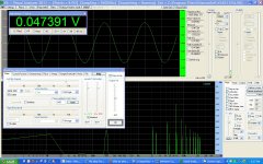
And finally, 6656 Hz clean:

At an earlier point, I had long wires (antennas) connecting many of the components and noticed it was picking up 60Hz from a nearby incandescent lamp. Switching the lamp off made some changes so it was obviously picking it up.
Soldering everything to a board practically eliminated it. However, there will always be some 60Hz from the PC power supply plus noise from the switchers, which I presume is what is seen in the "no input" screenshot.
The opamp is a self-contained audio preamplifier by ADI, #SSM2019 and beats making your own by a longshot. However, they insist tying across the +/- inputs with a "RF capacitor for stability.
The only RF source around is the router 10 feet away and the USB adapter in the back of the PC.
The ripple in the waveform graph at the top is actually moving backwards slowly, riding the sine. It is there for most frequencies of interest.
Ok, so there is noise entering the circuit. It must be gotten rid of, since it is only the first stage. There will probably be two more opamps, with a total maximum gain of 200 or more, depending on human speaker distance. This noise and the distortion it causes cannot be multiplied!
There is also the question of background noise or reflections of the speaker tone off the walls. I cannot see how reflections (reverberation) can produce significant lower frequencies, but this should be looked into. There is also the problem of the mic itself. It is picking up sound from the sides which it should not. Even though the elements were matched, I believe the differences in dropping resistors (1%) and the DC blocking caps (5%) are contributing.
A anechoic chamber might come in handy....
Thank you everyone for your input. Any further comments are welcomed.
Looking at it a bit more theoretically: under steady-state conditions, the response of a stable linear time-invariant system excited by a sine wave with frequency f will also be a sine wave with frequency f, but usually with different amplitude and phase. So if you find that some other frequency is produced, one of these conditions must be violated.
1. Maybe steady state has not been reached. Do you wait a few seconds between switching on the sine wave and determining the spectrum, to give your room time to settle?
I've never heard of self-oscillating rooms, so the stability will be OK.
2. Non-linearity: you have already considered background noises (which would make the room affine rather than linear). Vibrations of whatever supports the microphone maybe? The loudspeaker will generate some distortion, but normally only harmonic and no subharmonic distortion. Is there anything in your room that vibrates so strongly due to the test tone that it starts rattling?
3. About time variance: are there any moving parts that affect the room acoustics? Maybe a big fan? In any case, I would expect that to produce sidebands around the desired and not peaks at much lower frequencies.
MarcelvdG: Thank you for your reply. All those have been definitively ruled out. It is time to acquire a better audio card, at least one that has an ADC external to the DSP chip. It will not be a shielded card so I may make one for it.
I started to make a fully shielded enclosure for the circuitry, but ran out of copper foil. More will be here in two days.
Then, whatever is left will be my minimum, since I do not see myself trying to eliminate the power supply noise.
I tried to video the scope, but the processor would not handle both programs. I will switch to a faster machine, and install the new card in there.
I have come a long way. I found using a PC power supply on the bench produced too much noise. A screw-in florescent bulb on the bench also ruined everything. So now I have a Ni-Cd battery pack, and the bulb is gone. There is still a little 60Hz but it's hard to tell now if it is coming from the incandescent lamp or the PC power supply.
And perhaps I am expecting too much from a PC based scope...
Update
I am now running on a different machine. A Core i7 920. VA works much better and even works perfect on Debian Linux 64 bit (box stock). The sound card is the same. The old machine had an Athlon 1.8 single core.
The following has been observed:
-Noise is greatly reduced.
-DC offset is reduced, except it is below the X axis instead of above.
-The bothersome spikes lower than the fundamental are greatly reduced in number and magnitude, with either the mic or the VA wave generator as input.
-When the generator is running, one core is completely pinned at 100%!
Conclusion:
-Single core processor is no good for VA.
-The system board and power supply combination may influence performance.
-Sample rate adjustments should be made to reduce distorted waveforms at higher frequencies. FFT and Sample Rate must be adjusted in tandem. Changing one without the other renders the program unusable with some combinations. 8192 and 81920 worked good for me.
-An inexpensive sound card is probably sufficient for most needs. According to an evaluation I read, the high end sound cards are better all around and will offer a second channel. Mic inputs are mono. High may actually be an economical alternative to purchasing a real scope, for audio anyway....
- Status
- This old topic is closed. If you want to reopen this topic, contact a moderator using the "Report Post" button.
- Home
- Amplifiers
- Solid State
- Distorted waveform from PC microphone