Hello,(thanks for letting me in ).
I,ll try and keep to point.
I have a GM Delco 80bfmt1 8 track/am/fm radio.(pics below).On following the wiring diagram printed upside down on the top(i hope it was upside down) I tried to"just" power up on a 3 amp psu.
On turning the radio on,there was no radio backlight(bulb hollder, bulb all ok).
i stuck a simple tester ciruit tester (bulb) to where the power should leave the radio to power the antenna,still nothing.
I did hear a considerable difference in noise from the 3 amp psu,when radio is turned on position.
I assumed the radio was too much for the 3 amp psu and proceed to a 7 amp psu.
On switching on this time still the same,no light and no power from power ant output. However something did happen,so i turned it off and unplugged.I got that strong smell of something hot and a touch of smoke..
I took it apart and repowered to find out what was smoking,and located it to a blue with white stripe capacitor or resistor (my knowledge is minimal).Where the on/off volume switch sits on the board.Doesnt melt on the 3 amp psu...
Im am after knowing a few things at this stage,
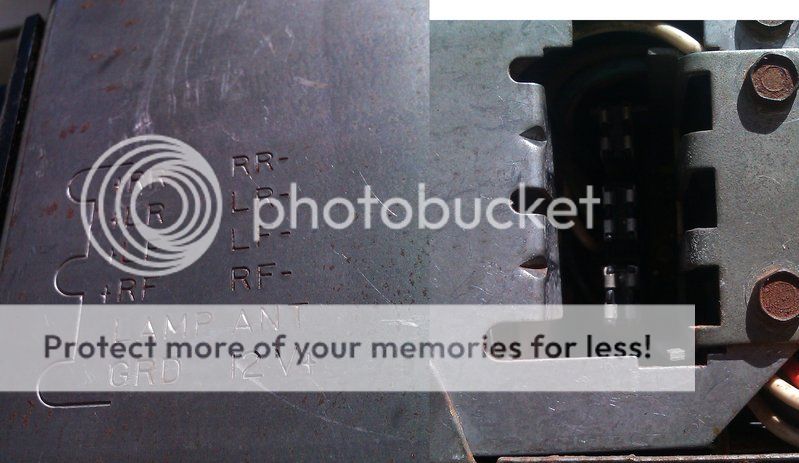
1) On the sockets at rear,one terminal,next to power ant output,states LAMP.what goes to or from?
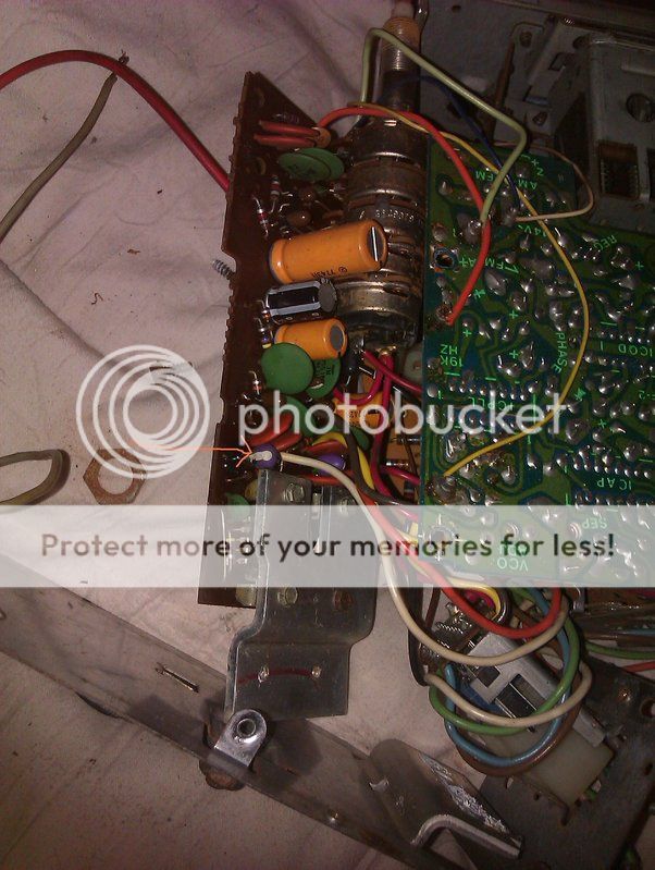
2) What is the blue and white item that melts,arrow pointing to item in bottom left photo. I,ll be needing another one.
3) Is there a proceedure i can follow to get it to power up,so i can see what works and what doesnt.
Many thanks for your time,

I,ll try and keep to point.
I have a GM Delco 80bfmt1 8 track/am/fm radio.(pics below).On following the wiring diagram printed upside down on the top(i hope it was upside down) I tried to"just" power up on a 3 amp psu.
On turning the radio on,there was no radio backlight(bulb hollder, bulb all ok).
i stuck a simple tester ciruit tester (bulb) to where the power should leave the radio to power the antenna,still nothing.
I did hear a considerable difference in noise from the 3 amp psu,when radio is turned on position.
I assumed the radio was too much for the 3 amp psu and proceed to a 7 amp psu.
On switching on this time still the same,no light and no power from power ant output. However something did happen,so i turned it off and unplugged.I got that strong smell of something hot and a touch of smoke..
I took it apart and repowered to find out what was smoking,and located it to a blue with white stripe capacitor or resistor (my knowledge is minimal).Where the on/off volume switch sits on the board.Doesnt melt on the 3 amp psu...
Im am after knowing a few things at this stage,
1) On the sockets at rear,one terminal,next to power ant output,states LAMP.what goes to or from?
2) What is the blue and white item that melts,arrow pointing to item in bottom left photo. I,ll be needing another one.
3) Is there a proceedure i can follow to get it to power up,so i can see what works and what doesnt.
Many thanks for your time,
I would like to add its not a case of its dead...I have to bring it back to life...
all the best
all the best
Last edited:
1) I don't know, but I'm curious to know what it is. It shouldn't affect operation and troubleshooting, though. My best guess is it connects to the dash dimmer.
2) Is that an identical blue & white part behind the white wire? They look like tantalum caps but it's hard to tell for sure.
3) You're basically on the right track. I'd stick with the 3 amp psu; that should be plenty for radio operation at moderate volume. Strong local AM stations may not even need an external antenna. You have checked for fuses? Use your tester to verify that power is actually making it to the circuit; I'm not sure I'd trust the Ant out. And old caps may be dried up and open. A multimeter would be helpful; a go-no go tester can only take you so far.
Thanks,spud/kev been trying to get unit lit up only to find " it is" illuminated via power from dash lights...ya right .
Yes there "was" an identical blue and white part behind white wire, and searching Tantalum caps,im sure thats what they were.On closer inspection they look green,coated purple,with a white paint mark.
I take it the white line was to notifty which side positive..There was no markings,numbers letters or anything else. Ive obviously got to find the correct ones,so how do i know which ones ?
I also managed to pop a vertical capicitor,yellow one below in pic,what number do i use ?
numbers listed
7898283 , 900uf,0-16vdc,7743h
all the best
Last edited:
Thank you Kev ,Spud, bulb powered up ,via lights ")
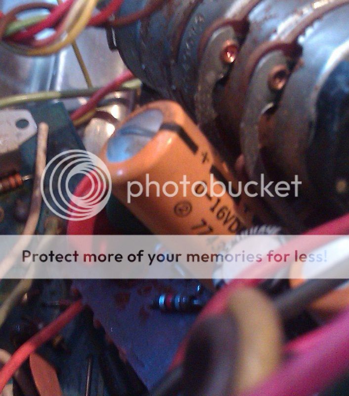
You can see a identical tantalum cap in pic,i searched google and thats what they look like,closer inspection shows theyre green ,coated purple,with a white painted line....im assuming that inotifies what side was positive ???
However that one blew too,there was no numbers letters or markings on them so how do i know which ones to get?
Ive also just blown the tall yellow capicitor,
Delco part no.7898283,900uf,0-16vdc,7743h......Unfortuately when i type in part number it comes back as a delco 900"mf"......can this be used?anyone know where to get these parts
all the best
According to this calculator it is a 750PF,
Tantalum Capacitor Color Code Calculator
But it seems that it is a 7.5 uf
I Can't see all of the colors but I am assuming a 9v or 16v
tantalum capacitor polarity - Google Search
http://pcbheaven.com/wikipages/Reading_Part_Values/
this one says 7.5pf,
http://pcbheaven.com/drcalculus/index.php?calc=capscolors
The first two colors are read as 75 in picofarads the white dot that runs into a stripe should be the multiplier of .1 unless there is another dot that we don't see in the photo.
So 7.5 pf seems to be the correct value Typically these caps shouldn't be bad in this circuit depending on what it is used for.
It could be just used in the feedback loop to keep the amp from oscillating as it is a very small value.
jer
Last edited:
7.5pF seems to me to be a bit small for a tantalum cap. It's surrounded by ceramic discs and it makes some sense that GM would have just stuck another couple in there at those positions. Unfortunately, 7.5µF isn't a standard value. 6.8µF and 8.2µF are closest, and either ought to work acceptably, or two could be placed in parallel eg 6.8µF & 1µF for 7.8µF. No less than 16V rating in any case.
Hi all,just like to say i really appriciate the time you,ve given me on here.
I know im a dumbass when it comes to electronics.Let me clue you up to my situation.
In the last two years i have learnt welding ,panel beating,leatherwork,mechanics,vehicle wiring, paintwork,and lpg conversions,(petrol being $10 a gallon here).I have removed all rust,changed every nut ,bolt,rubber and wire on my late fathers 1969 v8.Myself and my young son.


Im pleased with how its came out,its been a steep learning curve,it,s now come to this final peice,this 8 track radio.Ive applied the same principle to this radio,as i did the car,and i cannot get my head around it.I am in complete awe of you and your understanding of all this.
Logic states i should farm this unit out to be fixed,or just purchase another unit the same,but something inside me nags at me saying,ive come so far,i have to fix it,its dads old radio..
Im having trouble locating the tantalum beads to the values in the above thread,lowest i can find is 10uf,16v.,and as i have no idea and am in completely in your hands.
I also assume that once the above thread components are changed,others may fail too.
What causes these parts to fail?and what function of the unit do these parts work?
I bought a decent multimeter but i have no idea what im looking for...
Many thanks for all you time and brain grey matter
I know im a dumbass when it comes to electronics.Let me clue you up to my situation.
In the last two years i have learnt welding ,panel beating,leatherwork,mechanics,vehicle wiring, paintwork,and lpg conversions,(petrol being $10 a gallon here).I have removed all rust,changed every nut ,bolt,rubber and wire on my late fathers 1969 v8.Myself and my young son.
Im pleased with how its came out,its been a steep learning curve,it,s now come to this final peice,this 8 track radio.Ive applied the same principle to this radio,as i did the car,and i cannot get my head around it.I am in complete awe of you and your understanding of all this.
Logic states i should farm this unit out to be fixed,or just purchase another unit the same,but something inside me nags at me saying,ive come so far,i have to fix it,its dads old radio..
Im having trouble locating the tantalum beads to the values in the above thread,lowest i can find is 10uf,16v.,and as i have no idea and am in completely in your hands.
I also assume that once the above thread components are changed,others may fail too.
What causes these parts to fail?and what function of the unit do these parts work?
I bought a decent multimeter but i have no idea what im looking for...
Many thanks for all you time and brain grey matter
Tantalum capacitors are rarely used in values below 1uf. They are used where high capacitance in a small package is required. They are very sensitive to over-voltage and reverse voltage.
The electrolytic capacitors can be damaged in the same ways as mentioned above.
Are you sure that this radio wasn't connected to the power source with reverse polarity?
The electrolytic capacitors can be damaged in the same ways as mentioned above.
Are you sure that this radio wasn't connected to the power source with reverse polarity?
Someone may have connected it with reverse polarity before you received it.
The radio should work without those capacitors unless they're shorted. For testing, you can install virtually any cap with a value near the rating of the original.
Do you get any response from the radio if you connect a speaker?
The radio should work without those capacitors unless they're shorted. For testing, you can install virtually any cap with a value near the rating of the original.
Do you get any response from the radio if you connect a speaker?
Dave its not the light,it popped on the bench ,then hissed,.However i think it shorted out on the case,it was sitting on,big mistake.Maybe it's just the lighting, but it looks to me like the case of that electrolytic cap is bulging. Tell tale sign of reverse polarity being applied.
i ordered another one and a couple of tantalums .Im concerned that Perry said i should be getting something even with the bits blown ,but im getting nothing.. Thanks for ya time
I have now replaced the parts with 2 ITT 6.8/16v tants,and the 1000uf/25v capicitor.
Good news,its now not burning out when power gets to them,The downside is ,still no sound,not even a crackle.
Could it be a dry joint somewhere,is it advisable to go over all the old solder with my iron.
What is next i can test,i just bought a proper circuit tester.
Good news,its now not burning out when power gets to them,The downside is ,still no sound,not even a crackle.
Could it be a dry joint somewhere,is it advisable to go over all the old solder with my iron.
What is next i can test,i just bought a proper circuit tester.
I doubt resoldering all the joints will help. Did you test it in both radio and tape modes? No output at all suggests to me that a problem exists in the audio section, after either the radio or tape preamp sections. Without service literature, critical voltage checks and signal injection/tracing would likely be the most practical approach. Hopefully others here have more ideas.
- Status
- This old topic is closed. If you want to reopen this topic, contact a moderator using the "Report Post" button.
- Home
- General Interest
- Car Audio
- GM delco eight track 1970s 80bfmt1 problem