I'd like to get some expert opinions on my setup for linear distortion testing. Although not specifically Pass Labs related, I'm posting in this forum because I believe this is where I will actually find people who can provide insight and knowledge on this issues.
I finally acquired some testing "gear" that I can use to check frequency response and distortion for power amps (single ended mode only) that I am building and/or using. These can be chip amps, class AB or class D amps - pretty much anything I guess. The testing gear is a computer based scope and spectrum analyzer, as well as the usual multimeter. I know from a loopback test that the distortion and noise floor of the soundcard is very low (e.g. 0.0015% THD at 1k Hz) and the frequency response is very flat and wide.
I am using a dummy test load consisting of one or more 4-ohm non-inductive power resistors (100W) and one or more 3W 0.1 ohm metal film resistors, connected in series.
I am connecting the dummy resistor load to the single ended output, with the cold lead connected at the 0.1 ohm end of the load and the hot lead at the other. I connect the testing probe across the 0.1 ohm resistor only - this lets me connect directly to the computer (soundcard) inputs because the voltage drop across the 0.1 ohm resistor is 41 times (4 ohm load) or 81 times (8 ohm) LESS than the total voltage across the load, bringing it down within line level. I always check DC offset and make sure that I have the leads connected correctly so that the one probe is at ground potential.
The soundcard input connections are made with a half a cut up pair of cheap RCA interconnects, the wires of which are connected via sets of clip on leads across the 0.1 ohm resistor. The other half of the cut up interconnects are used to connect the soundcard output to the amplifier input via some additional clip on leads. In this way I can use an internal waveform generator to apply a pure sine wave tone to the amp inputs, and then get a voltage proportional to the amp output back into the computer, which I analyze with the spectrum analyzer to get distortion levels for each harmonic. I use different fundamentals between about 100 Hz and 10k Hz to check the distortion profile versus frequency.
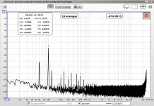
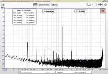
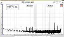
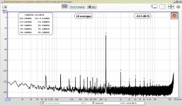
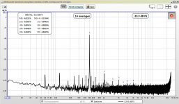
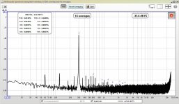
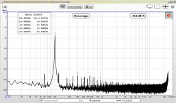
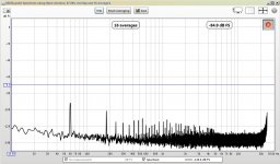
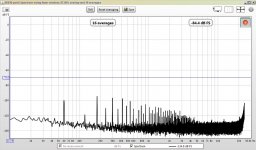
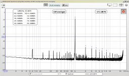
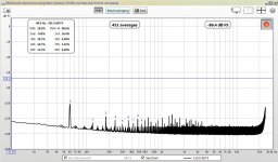
I've been able to conduct some preliminary tests, and they look OK. I tested an old Sanyo STK chip amp (a STK4141v, 25+25W, click me for datasheet) into 8 ohms and found moderate distortion levels (e.g. 0.15% at full power) dominated by second order. Lots of PS noise (mains frequency and overtones). Distortion was higher (e.g. 5 times higher) at frequencies below about 300Hz, dropping to about what I expected around 500Hz, and remaining low up to 10k Hz. I attached some plots of this. I also attached the spectrum taken with the amp on but input shorted, and with the amp off (noise floor). I have used this amp to power an active 2-way system and you could definitely hear the distortion in the lower octaves! This was part of the reason that I decided to start testing distortion levels...
Does my setup seem like a proper way to go about distortion and frequency response testing? What (if any) other things might I be concerned about?
Thanks for any and all advice!
-Charlie
I finally acquired some testing "gear" that I can use to check frequency response and distortion for power amps (single ended mode only) that I am building and/or using. These can be chip amps, class AB or class D amps - pretty much anything I guess. The testing gear is a computer based scope and spectrum analyzer, as well as the usual multimeter. I know from a loopback test that the distortion and noise floor of the soundcard is very low (e.g. 0.0015% THD at 1k Hz) and the frequency response is very flat and wide.
I am using a dummy test load consisting of one or more 4-ohm non-inductive power resistors (100W) and one or more 3W 0.1 ohm metal film resistors, connected in series.
I am connecting the dummy resistor load to the single ended output, with the cold lead connected at the 0.1 ohm end of the load and the hot lead at the other. I connect the testing probe across the 0.1 ohm resistor only - this lets me connect directly to the computer (soundcard) inputs because the voltage drop across the 0.1 ohm resistor is 41 times (4 ohm load) or 81 times (8 ohm) LESS than the total voltage across the load, bringing it down within line level. I always check DC offset and make sure that I have the leads connected correctly so that the one probe is at ground potential.
The soundcard input connections are made with a half a cut up pair of cheap RCA interconnects, the wires of which are connected via sets of clip on leads across the 0.1 ohm resistor. The other half of the cut up interconnects are used to connect the soundcard output to the amplifier input via some additional clip on leads. In this way I can use an internal waveform generator to apply a pure sine wave tone to the amp inputs, and then get a voltage proportional to the amp output back into the computer, which I analyze with the spectrum analyzer to get distortion levels for each harmonic. I use different fundamentals between about 100 Hz and 10k Hz to check the distortion profile versus frequency.
I've been able to conduct some preliminary tests, and they look OK. I tested an old Sanyo STK chip amp (a STK4141v, 25+25W, click me for datasheet) into 8 ohms and found moderate distortion levels (e.g. 0.15% at full power) dominated by second order. Lots of PS noise (mains frequency and overtones). Distortion was higher (e.g. 5 times higher) at frequencies below about 300Hz, dropping to about what I expected around 500Hz, and remaining low up to 10k Hz. I attached some plots of this. I also attached the spectrum taken with the amp on but input shorted, and with the amp off (noise floor). I have used this amp to power an active 2-way system and you could definitely hear the distortion in the lower octaves! This was part of the reason that I decided to start testing distortion levels...
Does my setup seem like a proper way to go about distortion and frequency response testing? What (if any) other things might I be concerned about?
Thanks for any and all advice!
-Charlie
Attachments
POWER SUPPLY HARMONICS
One thing that I (just now realized from the set of measurements shown above) is how much the power supply harmonics are effecting the distortion measurements.
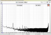
Look at the plots of "amplifier on but no signal applied" versus "noise floor" (you can hold you mouse over the images of the attachments before enlarging to see the file name). "Noise floor" is just the measurement system picking up electronic noise (the amplifier is off). It's mostly 60 Hz mains noise. When I turn on the amp but hold the input at ground, additional power supply harmonics show up. These are significant as high as 11th order (720Hz)! Wow.
I had been puzzled why the distortion was increasing for lower frequencies. I randomly chose 100Hz and 300Hz for "low" frequencies. I just realized that these have some harmonic components that correspond to the PS harmonics:
So it looks like I should remake the power supply. It is currently a small inline bridge (with a 4A current rating) and 3000uF caps on the rails. I have the parts around to replace these parts with a new bridge and a two stage PS like Nelson suggests for the F5 Turbo (Ah Ha, a Pass labs connection at last!), that is a first bank of caps, then a series resistor on the rail, then another bank of caps. This forms an RC low-pass filter and should reduce this junk. Probably just increasing the capacitance will reduce ripple and harmonics, which I assume are feeding through the chip amp due to a low PSRR.
Food for thought...
-Charlie
One thing that I (just now realized from the set of measurements shown above) is how much the power supply harmonics are effecting the distortion measurements.
Look at the plots of "amplifier on but no signal applied" versus "noise floor" (you can hold you mouse over the images of the attachments before enlarging to see the file name). "Noise floor" is just the measurement system picking up electronic noise (the amplifier is off). It's mostly 60 Hz mains noise. When I turn on the amp but hold the input at ground, additional power supply harmonics show up. These are significant as high as 11th order (720Hz)! Wow.
I had been puzzled why the distortion was increasing for lower frequencies. I randomly chose 100Hz and 300Hz for "low" frequencies. I just realized that these have some harmonic components that correspond to the PS harmonics:
- For 100Hz, the 3th harmonic of the fundamental is at the same frequency as the 5th PS supply harmonic (300Hz) and the 6th harmonic of the fundamental is at the same frequency as the 10th PS supply harmonic (600Hz). Sure enough, beyond 2nd order the 3rd and 6th orders seem high.
- For the 300 Hz measurement, the second harmonic (600Hz) of the 300Hz fundamental is the same as the 10th PS supply harmonic. Again, the measured distortion harmonic seems oddly high.
So it looks like I should remake the power supply. It is currently a small inline bridge (with a 4A current rating) and 3000uF caps on the rails. I have the parts around to replace these parts with a new bridge and a two stage PS like Nelson suggests for the F5 Turbo (Ah Ha, a Pass labs connection at last!), that is a first bank of caps, then a series resistor on the rail, then another bank of caps. This forms an RC low-pass filter and should reduce this junk. Probably just increasing the capacitance will reduce ripple and harmonics, which I assume are feeding through the chip amp due to a low PSRR.
Food for thought...
-Charlie
Last edited:
F5 TURBO power supply question
OK, here's an actual question (maybe for NP himself):
In your F5 Turbo power supply, with the RC filtering of the rails, what kind of sane limits should be put on the series resistor? The larger the resistor, the more filtering, but also more voltage drop and perhaps reduced "recharge" rate of the second set of caps.
So, how does one decide just how large the resistor can be, or what tradeoffs should be considered? Any relevant math or handwaving is welcome.
-Charlie
So good so far. You will probably refine all this down the line, but you'll
know why when you do it.
The power supply noise thing is a matter of actual supply noise and also
the ability of the circuit to reject that noise (the PSRR - Power Supply
Rejection Ratio - as distinguished from PFRR, the Propositions to Females
Rejection Ratio).
If you have more noise in the supply, you need more PSRR, and vice versa.
The other thing you have to watch out for is that some of those line
harmonics may relate to any ground loops between the amplifier and the
computer system. I occasionally have to lift AC Earth connections on the
power cords to get that down.
As to resistance values, I usually use either nothing at all or .1 to .5
ohms depending on the amount of power and the capacitance involved.
What results would you get if you just measured the amp output with the input connected via a long lead to a remote 100ohm dummy source?
That may let you experiment with cable routing and PSU adjustments to reduce the mains fundamental and harmonics.
Yes, I know, its a big antenna... and the input wire is not shielded, and the amp is a plate amp type so the input wiring is not inside a metal enclosure.
NP: probably not a mains ground loop. Mains connection is a polarized (2-prong) plug only. Perhaps a ground loop at the line (input) level? I am connecting the output ground back to the soundcard.
Here is my plan for revamping this:
1. Remove existing PS caps and bridge
2. Wire up external bridge and caps and connect then at the current PS cap location on the amp board
3. create star ground on PS
4. route speaker return (grounds) to star instead of through amp board
5. route a separate ground wire to line level grounds on amp board
6. replace input cable with shielded coax (Belden 1505A)
This should result in reduced noise and hum...
-Charlie
Results for REV 1 power supply
I've completed testing of "REV 1" of the power supply. Originally my plan was the following (with added comments in blue):
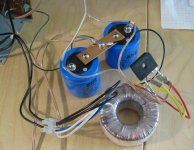
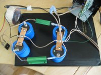
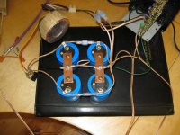
I've attached a picture of the power supply. I wired up an 8A, 200 PIV inline bridge rectifier (I have a gross of these lying around so I put one to good use) and used two screw terminal 10,000uF (-10%/+75%) caps with a heavy copper buss bar for the ground connection in between. On the buss bar I created a star ground point, to which I connected
a. the transformer center tap
b. a ground wire that connects to all the ground on the PCB
c. the returns for the speaker connections
This is not a grounded power supply, otherwise earth/safety ground would be connected here, too. I bypassed the speaker fuses that were part of the previous signal flow. I also removed the existing input cabling (unshielded) and added two small screw terminal blocks to which I could directly connect a shielded cable.
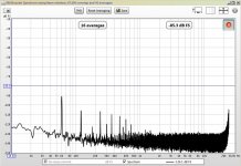
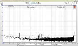
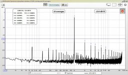
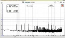
I connected the dummy load (8 ohm configuration) as before and remeasured the distortion at the same frequencies used previously, as well as with no signal input, and the amp off and caps drained to give an idea of the measurement noise floor. See attached plots. The new PS has made a large difference in the 100 Hz - 500 Hz distortion levels, which now measure quite low:
100 Hz: 0.0158%
300 Hz: 0.0130%
500 Hz: 0.0222%
1k Hz: 0.0385%
5k Hz: 0.145%
10k Hz: 0.257%
Not sure why distortion at 5k and 10k Hz is high, but I can live with it for now.
So, this is a great improvement. Also the noise floor with the amp on but no input signal is much lower. All components at -115dB or so. That's a 25dB reduction for 60 Hz, and about 10 dB for the harmonics. This may partly be due to the use of shielded input cabling and a shielded measurement probe.
The REV 1 power supply is just the standard fare unregulated dual rail setup. I'm hoping to add two more caps and a couple of series resistors on the rails for REV 2, which will be similar to the power supply for the F5 Turbo that NP outlined in the build notes. It will be interesting to compare the two versions.
Anyway, quite an improvement so far, and now a very nice little amp! These measurements were done into an 8 ohm load with PS rails around +/-32VDC. The amplifier IC is able to deliver about 40W per channel under these conditions.
-Charlie
.
I've completed testing of "REV 1" of the power supply. Originally my plan was the following (with added comments in blue):
1. Remove existing PS caps and on-board bridge rectifier [DID THIS]
2. Wire up external bridge and caps and connect them at the current PS cap location on the amp board [DID THIS]
3. create star ground on the new PS [DID THIS]
4. route speaker return (grounds) to star instead of through amp board [DID THIS]
5. route a separate ground wire to line level grounds on amp board [ALL GROUND ARE CONNECTED ON THE PCB SO CAN'T SEPARATE POWER AND SIGNAL GROUNDS]
6. replace input cable with shielded coax (Belden 1505A) [DID NOT DO THIS (YET)]
-Charlie
I've attached a picture of the power supply. I wired up an 8A, 200 PIV inline bridge rectifier (I have a gross of these lying around so I put one to good use) and used two screw terminal 10,000uF (-10%/+75%) caps with a heavy copper buss bar for the ground connection in between. On the buss bar I created a star ground point, to which I connected
a. the transformer center tap
b. a ground wire that connects to all the ground on the PCB
c. the returns for the speaker connections
This is not a grounded power supply, otherwise earth/safety ground would be connected here, too. I bypassed the speaker fuses that were part of the previous signal flow. I also removed the existing input cabling (unshielded) and added two small screw terminal blocks to which I could directly connect a shielded cable.
I connected the dummy load (8 ohm configuration) as before and remeasured the distortion at the same frequencies used previously, as well as with no signal input, and the amp off and caps drained to give an idea of the measurement noise floor. See attached plots. The new PS has made a large difference in the 100 Hz - 500 Hz distortion levels, which now measure quite low:
100 Hz: 0.0158%
300 Hz: 0.0130%
500 Hz: 0.0222%
1k Hz: 0.0385%
5k Hz: 0.145%
10k Hz: 0.257%
Not sure why distortion at 5k and 10k Hz is high, but I can live with it for now.
So, this is a great improvement. Also the noise floor with the amp on but no input signal is much lower. All components at -115dB or so. That's a 25dB reduction for 60 Hz, and about 10 dB for the harmonics. This may partly be due to the use of shielded input cabling and a shielded measurement probe.
The REV 1 power supply is just the standard fare unregulated dual rail setup. I'm hoping to add two more caps and a couple of series resistors on the rails for REV 2, which will be similar to the power supply for the F5 Turbo that NP outlined in the build notes. It will be interesting to compare the two versions.
Anyway, quite an improvement so far, and now a very nice little amp! These measurements were done into an 8 ohm load with PS rails around +/-32VDC. The amplifier IC is able to deliver about 40W per channel under these conditions.
-Charlie
.
Attachments
Do not locate the Main Audio Ground on the smoothing cap Zero Volt Bus.
You must separate those two to ensure separation of the charging pulses from the audio signals referencing the Main Audio Ground.
OK... then where do you suggest that I locate it (the audio or line level ground)? What other grounding point is there?
Remember, there is no earth ground in this system. It uses the "polarized" plug that is common in the US with low power equipment.
-Charlie
Might try testing with MultiTones -- If you can find the software/hardware to do it.
Also take a look at your whole system.... measure the thd/harmonic/Im from source to speaker terminals of the power amp. get the whole distortion data for your entire system -- as that is what you are actually hearing. That total distortion level can tell you a lot... like which harmonics are dominate and where the most improvement could be done. -RNMarsh
Also take a look at your whole system.... measure the thd/harmonic/Im from source to speaker terminals of the power amp. get the whole distortion data for your entire system -- as that is what you are actually hearing. That total distortion level can tell you a lot... like which harmonics are dominate and where the most improvement could be done. -RNMarsh
Locate the Main Audio Ground (MAG) somewhere near all the ground references/connections that the amplifier needs. None on these are on the chassis.
Now run a connection from that MAG to the PSU Zero Volts on that nice big useless buss bar.
Run another connection from MAG to all the exposed metal parts, ready for when you mount it all inside a box.
Now run a connection from that MAG to the PSU Zero Volts on that nice big useless buss bar.
Run another connection from MAG to all the exposed metal parts, ready for when you mount it all inside a box.
Might try testing with MultiTones -- If you can find the software/hardware to do it.
Also take a look at your whole system.... measure the thd/harmonic/Im from source to speaker terminals of the power amp. get the whole distortion data for your entire system -- as that is what you are actually hearing. That total distortion level can tell you a lot... like which harmonics are dominate and where the most improvement could be done. -RNMarsh
Hi RN in Cool,
I am only focusing on linear distortion testing at this point. I carry out testing on DIY loudspeakers that I build and I'm aware that the loudspeaker will likely have 10x more distortion that a middle of the road amplifier. As a result, I don't plan to get too serious about other parts of the reproduction chain until things are much farther down the road.
At the moment I am checking out this chip amp that was part of a PA (karaoke?) plate amp. I have a bunch of them, and they are convenient for my needs, so I want to explore the performance limits/limitations. I'd like see how I can clean up the output in various configurations and loads so that I know how to best put them to use.
-Charlie
Might try testing with MultiTones -- If you can find the software/hardware to do it.
Also take a look at your whole system.... measure the thd/harmonic/Im from source to speaker terminals of the power amp. get the whole distortion data for your entire system -- as that is what you are actually hearing. That total distortion level can tell you a lot... like which harmonics are dominate and where the most improvement could be done. -RNMarsh
Where is the LIKE button??
Locate the Main Audio Ground (MAG) somewhere near all the ground references/connections that the amplifier needs. None on these are on the chassis.
Now run a connection from that MAG to the PSU Zero Volts on that nice big useless buss bar.
Run another connection from MAG to all the exposed metal parts, ready for when you mount it all inside a box.
I perceive this as an unfriendly, unhelpful, and somewhat insulting post.
-Charlie
more data, more questions
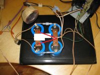
I moved on the the next revision of the power supply to see what changes and improvements could be gained. First, I added two more 10k caps, and used a 1.2 ohms series resistor on each rail in between the "first' set of caps, and the "second" set. I continue to use the "useless" buss bar, since it is at least convenient for making connections...
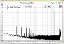
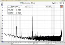
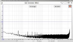
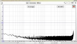
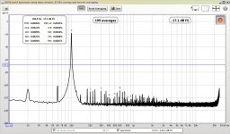
So, very different results than what I was expecting! The PS with the inline resistors (forming an RC lowpass filter with corner frequency no higher than 13Hz) did have much reduced ripple at 120Hz, but lots of higher frequency noise or harmonics shot up considerably! The mains noise (60Hz) was also higher. See attached plot of the amplifier on but with no input signal, and the measurement noise floor.
Not only that, but the distortion performance across the board was worse, too. For instance, at 1kHz the distortion increased to 0.0574% from 0.0385%. Similar changes happened across the board.
So, while ripple was reduced, everything else is worse. I had imagined that the RC filter would kill all higher frequency noise and that the additional caps would be beneficial.
Perhaps the additional wiring is just creating more "antennas" that can pick up noise? I did try to reposition the components in an attempt to improve this but it did not help. Everything is just sitting on the desk next to my computer, so noise pickup is a possibility...
Thoughts?
-Charlie
I moved on the the next revision of the power supply to see what changes and improvements could be gained. First, I added two more 10k caps, and used a 1.2 ohms series resistor on each rail in between the "first' set of caps, and the "second" set. I continue to use the "useless" buss bar, since it is at least convenient for making connections...
So, very different results than what I was expecting! The PS with the inline resistors (forming an RC lowpass filter with corner frequency no higher than 13Hz) did have much reduced ripple at 120Hz, but lots of higher frequency noise or harmonics shot up considerably! The mains noise (60Hz) was also higher. See attached plot of the amplifier on but with no input signal, and the measurement noise floor.
Not only that, but the distortion performance across the board was worse, too. For instance, at 1kHz the distortion increased to 0.0574% from 0.0385%. Similar changes happened across the board.
So, while ripple was reduced, everything else is worse. I had imagined that the RC filter would kill all higher frequency noise and that the additional caps would be beneficial.
Perhaps the additional wiring is just creating more "antennas" that can pick up noise? I did try to reposition the components in an attempt to improve this but it did not help. Everything is just sitting on the desk next to my computer, so noise pickup is a possibility...
Thoughts?
-Charlie
Attachments
yet another twist...
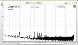
More changes produced "REV 3" of the PS.
I decided to remove the series resistors on the rails, but to keep the second set of caps in place. This produced the following changes:
the ripple harmonic (120Hz) returned
the mains noise (60Hz) was reduced with respect to REV 2
the higher frequency noise/harmonics increased with respect to REV 2
the 1k Hz distortion returned to the level found for REV 1 of the PS
So, to rank the performance in terms of noise and ripple, from best to worst:
REV 1 (single set of caps)
REV 2 (two sets of caps with a 1.2R series resistor on the rails)
REV 3 (two sets of caps directly connected at rails)
When two sets of caps were used, I connected the buss bars with wire. The transformer center tap is connected at the buss bar of the first set of caps. The speaker returns and a ground wire that leads to the PC board are connected on the second buss bar.
So, what's up here? Is layout a problem? As I add more "stuff" am I just picking up more noise or is it being generated in the/by the components that I am adding??? I have not found many good resources on the physical layout of a power supply like this, so I did not think it would be terribly important.
-Charlie
Attachments
stick in a whole bunch of 1u and 0.1f bypass caps,, then put a bunch of ferrites and common mode chokes, faraday cages, twisted pairs, snubbers, MOVs, mains filters, dc blockers, , --,--, etc.
Then do it all again with the resistors back in place.
only joking, but you do have a large can of worms there...maybe it should be a can of Guinness. the very best of luck to you, it would be great to have a definitive answer.
(this thread is going to be better than the ryder cup!)
Then do it all again with the resistors back in place.
only joking, but you do have a large can of worms there...maybe it should be a can of Guinness. the very best of luck to you, it would be great to have a definitive answer. (this thread is going to be better than the ryder cup!)
OK, I followed Zen Mod's suggestions (except for the one about running the ground wires to the PCB instead of to the star ground). Unfortunately there was no real change in the level of mains noise/harmonics.
I then tore down the PS and re-wired it in the "REV 1" configuration with a new bridge (in case I slightly toasted one of the diodes or something...). I also built a new shielded input cable from coax in case that was where noise was creeping in. When I connected everything and powered up again, the mains noise and harmonics were still there to some extent, not as low as I originally measured when testing REV 1. I actually did try to insert some 10-100nF ceramic caps in the secondary and this had absolutely no effect on the harmonics. Hmmm.
Then something dawned on me.. it got pretty hot out there today (100F) and maybe this is just due to dirty mains power??? Not sure, but as of right now it's early evening and people are likely hunkered down with lots of air conditioning on, etc. I will have to remeasure in the morning, and if this happens again see if a line filter will help.
This "REV 1" power supply (single pair of caps connected via a buss bar, with all grounds connected there) seems simple and effective, so why make things more complicated? I am getting lower distortion (THD) levels, such as:
100 Hz: 0.005%
300 Hz: 0.005%
500 Hz: 0.007%
1k Hz: 0.016%
5k Hz: 0.07%
10k Hz: 0.087%
These distortion figures meet the design spec of the amp, as specified in the data sheet, so I am feeling good about this result. This is at "full power". I actually measured the RMS voltage with a voltmeter (albeit a crappy one) and that was about 16V, which corresponds to 32W of power. I'll take it!
I will try to post more info when I have it.
-Charlie
- Status
- This old topic is closed. If you want to reopen this topic, contact a moderator using the "Report Post" button.
- Home
- Amplifiers
- Pass Labs
- AMPLIFIER TESTING: HOW-TO QUESTIONS