Hi All, I'm repairing a Cadence TXA6004 amplifier.
Also, what should I be using as a ground point for the meter? I know if I'm working on the power supply's input-side I can use the power ground. On the power supply secondary side, I use the center terminal of the power transformer right?
- During triage I found blown output transistors on channel 3.
- Removed blown transistors.
- Tested amp - after the power-on mute released, a 220ohm resistor which connects the emitters of the two driver transistors smoked out.
- Installed new outputs and new resistor.
- Tested amp - after the power-on mute released the protection light came on.
- Removed the driver transistors for the channel (2SB631k and 2SD600k) Both tested good on DMM diode setting.
- Tested amp - powers on without protection light, audio sounds good through channels 1, 2 and 4.
Also, what should I be using as a ground point for the meter? I know if I'm working on the power supply's input-side I can use the power ground. On the power supply secondary side, I use the center terminal of the power transformer right?
Last edited:
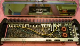
Cadence TXA6004 - channels outlined
Here ya go Perry - sorry for the delay, but it was naptime...
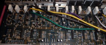
After naptime I checked the smaller transistors (the driver's drivers) above the drivers, and they appear completely shorted, typical transistor failure mode, which is what I had been expecting and looking for, just didn't find as quickly as I'm used to.
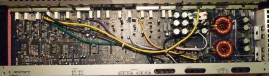
When the client brought these in, he was bragging on them. I like that its all through-hole components (no SMD), and the boards are neat in that you can see the bottom traces from the top, but the plating is crap - the pad plating breaks off from the transistors with very little heat, plus the holes are split on the ends, and there isn't a plated through-hole on the whole board. The heatsinks don't make sense either. A reasonable amount of surface area, but when the case is assembled there is no way for air to flow through them. Neither convection or breeze. No heatsinking on the drivers either. And they were all sort of randomly crooked too. And on the solder side everytime they bent a lead to hold the component in, they bent it over another trace.
Then I googled 'em up and found that these amps were a big embarrassment to Cadence because they failed easily. The redesigned ones have some circuit changes and longer heatsink fins.
Here ya go Perry - sorry for the delay, but it was naptime...
After naptime I checked the smaller transistors (the driver's drivers) above the drivers, and they appear completely shorted, typical transistor failure mode, which is what I had been expecting and looking for, just didn't find as quickly as I'm used to.
When the client brought these in, he was bragging on them. I like that its all through-hole components (no SMD), and the boards are neat in that you can see the bottom traces from the top, but the plating is crap - the pad plating breaks off from the transistors with very little heat, plus the holes are split on the ends, and there isn't a plated through-hole on the whole board. The heatsinks don't make sense either. A reasonable amount of surface area, but when the case is assembled there is no way for air to flow through them. Neither convection or breeze. No heatsinking on the drivers either. And they were all sort of randomly crooked too. And on the solder side everytime they bent a lead to hold the component in, they bent it over another trace.
Then I googled 'em up and found that these amps were a big embarrassment to Cadence because they failed easily. The redesigned ones have some circuit changes and longer heatsink fins.
Not so lucky
Ok, pulled the drivers drivers, I had seen + and - 29 across all 3 pins of each (respectively npn/pnp) so I thought they were blown, but no, apparently they were just full on as I left them out, powered up and measured at the pads, finding the base pads at +&-29. Hmmm. Its coming from somewhere.
Anybody got schematics for Cadence?
Time to check voltage at every transistor in the area...
Although I already tested them on Diode-check earlier for shorts, so maybe a shorted op-amp on the channel?
Last edited:
When I first put in the replacement outputs I remember hearing white noise through my test speakers before the protect light came on - and up to now I hadn't paid attention to that info, but, perhaps one of the op-amps is either shorted, or operating at infinte gain (no feedback)?
I was supposed to get a nice scope last weekend (didn't work, had to repair it, but a scope none-the-less) but life interferred with those plans...
I was supposed to get a nice scope last weekend (didn't work, had to repair it, but a scope none-the-less) but life interferred with those plans...
#6:
This appears to be a generic Asian design. If you can post a high quality photo of the power supply control area and one of the power amplifier channels, I'll see what I have that's close.
#7:
'Large' amps are those that require 4 or more hours to disassemble, remove and replace part and reassemble. An amp like this wouldn't be in that group. This amp should be easily repairable.
#8:
You can look at the signal coming from the op-amp feeding the power amplifier section. Without a scope, you may need a signal tracer. You may be able to use a multimeter to compare the signal to the other channels (with the same settings for xo freq, gain, etc...).
- Status
- This old topic is closed. If you want to reopen this topic, contact a moderator using the "Report Post" button.
- Home
- General Interest
- Car Audio
- Cadence TXA6004 Repair