perhaps no difference.
The DCR will be the sum of the two coils vs the DCR of the greater number of turns for the larger coil. Might be identical. Turns is turns. The specs may be published. Either way a trivial difference compared to bumping up to a fatter wire gauge.
What may make a difference is mutual coupling between the two coils depending on how you lay it out. But if they are in the same axis, or some distance apart there should be nil difference. Having them inadvertently in opposition will reduce the inductance.
I wouldn't waste any time or effort worrying about it.
_-_-bear
You can look at f.ex. this Madisound table and see that the DCR for two smaller coils in series do not add up to the DCR of one larger coil. Turns ain't always turns....
If you mount the two smaller coils so that they mutually couple, then the total inductance will be larger than their individual values.
If you mount the two smaller coils so that they mutually couple, then the total inductance will be larger than their individual values.
Last edited:
Hello,
I'm interested if anyone knows is there a difference in sound in a serial connection of two coils (Mundorf
CFC14 0,22uH + Mundorf CFC14 0,10uH) compared to one of larger value (Mundorf CFC14 0,32uH).
Thanks.
Hi,
There should be no difference, but if the 0.1 is not ~
half the size of the 0.22 you are wasting money.
rgds, sretern.
You can look at f.ex. this Madisound table and see that the DCR for two smaller coils in series do not add up to the DCR of one larger coil. Turns ain't always turns....
If you mount the two smaller coils so that they mutually couple, then the total inductance will be larger than their individual values.
The thing is that I bought 4 pcs of CFC14/0,22uH and now i need for my other project values of 0,32uH.
If i can connect them in series 0,22+0,10=0,32uH and without loosing sound quality i will do it. The RDC of 0,10uH is 0,07Ohm, 0,22uH is 0,11Ohm.
Well, to me it would be a matter of the damping factor (DF)
If an amp has a (assumption) DF of 1000 it's output impedance is 0.008 ohm
Add 0.1 ohm for the speaker wire and the DF drops to 74.1, not good
Add the 2 coils DCR (0.22 + 0.11 ohm) and the DF is 18.25, not good at all!
At this DF the speaker will do what it wants to do, not what the amp tells it
In a low power system that will not matter much, but that is why high-power systems use active Xovers and multiple power-amps. E
Before I get clobbert about my post (#11): I ignored complex ZCLR references as these would be meaningless without the full details of parts used and a schematic. E
I need it for very simple 2nd order Butterworth passive crossover.
Therefore, 0.22uH/0.11Ohm RDC + 0.10uH/0.07Ohm, sum will be 0.32uF/0.18Ohm (I can live with that), but what abouth quality of sound

I have Mundorf colis CFC14 0.22uH(and if possible I would love to use them), dont want to waste money buying coils of 0.10uH and connect to my coils if the quality of sound is not equal or similar to single coil of 0,32uH.
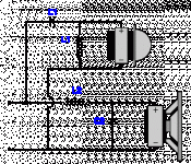
Attachments
a whole lot depends on things other than the coils.
the quality of the drivers is paramount.
then the enclosure, and its shape and construction.
finally the xover.
the xover must take into account the acoustic response of the drivers before during and after the intended xover frequency.
Frequently a 2nd order xover will not actually be that when the acoustic response of the driver + xover is measured.
One minor advantage of two coils is the option of changing the xover and/or reusing the coils later for something else.
_-_-bear
They will give less than the total nominal inductance if placed next to each other, no matter of orientation, about 10% less. I suspect this is caused by interaction of the magnetic fields. DCR will be higher than a larger coil of the same value due to difference in lenght of wire and core. Larger coils usually need a larger core, there is a formula for the most efficient way of winding to use the least amount of wire. If you place them at least 10cm away of each other, you will get the inductance as the nominal value of L1 + L2.
Two coils wired in series and mounted near each other can have a total inductance which is more or less than the sum of their individual inductances. This is caused by their mutual inductance, which either adds or subtracts depending on winding sense and orientation.Mario Pankov said:They will give less than the total nominal inductance if placed next to each other, no matter of orientation, about 10% less. I suspect this is caused by interaction of the magnetic fields.
This link might give some insight into the comments that, if you use two coils, the placement will effect the result in a unpredictable manner.
Placement of coils in crossover networks
Placement of coils in crossover networks
thanks, this is very helpful.This link might give some insight into the comments that, if you use two coils, the placement will effect the result in a unpredictable manner.
Placement of coils in crossover networks
Regards,
V.
Just did a quick check out of curiosity, two 0.56mH coils give 1.43mH ( +/- 3% stated accuracy for my RLC meter ) when on top of each other. DF96 made a good statement - depends on which end of the coils you connect, one side gives 1.05mH, when reversed its 1.18mH. Seems quite tricky if you don`t measure them.
- Status
- This old topic is closed. If you want to reopen this topic, contact a moderator using the "Report Post" button.
- Home
- Design & Build
- Parts
- Need help with coils in serial connection