@DIYAudio folks
I've been keeping this project log on another site but thought you guys may be interested as well so I decided to post it again here. As this project is on-going I'll keep both sides updated.
EDIT: The post won't show up properly here so here's the link to my original post:
http://www.head-fi.org/t/619661/a-students-attempt-at-the-plasmasonic-headphones
Last edited:
to post images you have to use the feature in the "Advanced" (normal, not the fast reply at the end of the thread) version where it says manage attachments... or you can link to another website elsewhere.
_-_-bear
PS. What you show in the link (when cut and pasted) "http://i.imgur.com/mZSoO.jpg" is Gerald Shirley's Corona Wind Speaker, that can be seen in the JAES Loudspeakers I Anthology. It dates from the 50's. Doesn't work particularly well... and I would not suggest it for headphones.
_-_-bear
PS. What you show in the link (when cut and pasted) "http://i.imgur.com/mZSoO.jpg" is Gerald Shirley's Corona Wind Speaker, that can be seen in the JAES Loudspeakers I Anthology. It dates from the 50's. Doesn't work particularly well... and I would not suggest it for headphones.
Last edited:
Thanks, I guess I'll just link it back to my post on the other site.
I can see how this idea would not work as a speaker because the air pressure it could generate is very limited. My design is based on the Plasmasonic1 headphones (a few decades ago) and they claimed it to work, So I'm determined to test this out.
I can see how this idea would not work as a speaker because the air pressure it could generate is very limited. My design is based on the Plasmasonic1 headphones (a few decades ago) and they claimed it to work, So I'm determined to test this out.
sure you have a better shot at a headphone... but the size of the array will need to be fairly large, and you will also emit a huge amount of ozone in an enclosed space next to your ears... maybe not so good?
No need to run away...
Got a link to those headphones?
Was this a commercial product?
You might want to look into the Hill Plasmatronic loud speaker... a bit different, but similar...
anyhow you will need a large number of emitting points... to start to get sound...
_-_-bear
No need to run away...
Got a link to those headphones?
Was this a commercial product?
You might want to look into the Hill Plasmatronic loud speaker... a bit different, but similar...
anyhow you will need a large number of emitting points... to start to get sound...
_-_-bear
sure you have a better shot at a headphone... but the size of the array will need to be fairly large, and you will also emit a huge amount of ozone in an enclosed space next to your ears... maybe not so good?
No need to run away...
Got a link to those headphones?
Was this a commercial product?
You might want to look into the Hill Plasmatronic loud speaker... a bit different, but similar...
anyhow you will need a large number of emitting points... to start to get sound...
_-_-bear
Yes, link to the Plasmasonic1 was in my original post.
but for your convenience: Plasmasonic
Ok, now I see the link...
You should stop and take a moment to breathe and think.
The power supply you built is unsafe.
What you want is a multiplier that uses high voltage diodes and high voltage, low capacitance (like 2000pf or so) high voltage ceramic discs. The thing you have built is DEADLY.
DO NOT CONTINUE UNTIL YOU LEARN SOME MORE - Please.
Also the caps will blow out, since they can not handle the peak voltages they may see...
You will NEED some very high Megohm, high voltage rated resistors. You must use them. If for some reason you do not know what you need them for, that alone is enough of a reason to stop your experiment now.
The thing you have built is hyper dangerous as it stands.
You can make it safe, but this is not a trivial thing - your life is at risk at this voltage level with the current you can discharge from that supply (or so it seems, as it looks from the images - I didn't see a schematic, if you posted it).
Please take this seriously.
Thanks.
_-_-bear
PS. it is a worthwhile thing to try... but you have to know how to not kill urself in the process!
Ok, now I see the link...
You should stop and take a moment to breathe and think.
The power supply you built is unsafe.
What you want is a multiplier that uses high voltage diodes and high voltage, low capacitance (like 2000pf or so) high voltage ceramic discs. The thing you have built is DEADLY.
DO NOT CONTINUE UNTIL YOU LEARN SOME MORE - Please.
Also the caps will blow out, since they can not handle the peak voltages they may see...
You will NEED some very high Megohm, high voltage rated resistors. You must use them. If for some reason you do not know what you need them for, that alone is enough of a reason to stop your experiment now.
The thing you have built is hyper dangerous as it stands.
You can make it safe, but this is not a trivial thing - your life is at risk at this voltage level with the current you can discharge from that supply (or so it seems, as it looks from the images - I didn't see a schematic, if you posted it).
Please take this seriously.
Thanks.
_-_-bear
PS. it is a worthwhile thing to try... but you have to know how to not kill urself in the process!
Alright Thanks.
The values of the capacitor and diodes were calculated as follows:
Max voltage of each capacitor is 110V * 1.414 * 2 = 311V
Used 400V capacitors and 1000V diodes.
The power supply is designed to have 1% ripple and 8% regulation @ full load.
Calculated capacitance is 29.xx µF (Used 33µF)
I AM actually aware that I need a resistor at the outputs to limit current because of the charge in the capacitors. That will be installed before I progress any further in this project.
But besides that I don't see anything wrong with the components, mind explaining a little?
load?
what load??
ur supposed to be drawing microamps?
what happens when ur resistor fails or arcs or shorts?
As I said this is a dangerous project, and you've built a power supply that if discharged across you might well kill you instantly.
Others reading might wish to comment?
_-_-bear
what load??
ur supposed to be drawing microamps?
what happens when ur resistor fails or arcs or shorts?
As I said this is a dangerous project, and you've built a power supply that if discharged across you might well kill you instantly.
Others reading might wish to comment?
_-_-bear
load?
what load??
ur supposed to be drawing microamps?
what happens when ur resistor fails or arcs or shorts?
As I said this is a dangerous project, and you've built a power supply that if discharged across you might well kill you instantly.
Others reading might wish to comment?
_-_-bear
The load is the amplifier which requires microamps to work.
I see your point, I'l put this on-hold until I learn more on the topic.
Thanks.
got schematic?
it is worthwhile to discuss it, there are a lot of other folks here besides me - I just noticed the post and decided to follow up - who may have good input and ideas for you.
_-_-bear
PS. have you considered an electrostatic headphone for a project? It has many of the same basic building blocks...
it is worthwhile to discuss it, there are a lot of other folks here besides me - I just noticed the post and decided to follow up - who may have good input and ideas for you.
_-_-bear
PS. have you considered an electrostatic headphone for a project? It has many of the same basic building blocks...
got schematic?
it is worthwhile to discuss it, there are a lot of other folks here besides me - I just noticed the post and decided to follow up - who may have good input and ideas for you.
_-_-bear
PS. have you considered an electrostatic headphone for a project? It has many of the same basic building blocks...
I have a rough sketch on paper, I'll draw it on the my computer for better legibility later today.
Yes I have, but my dad is making one now so it seems redundant for me to do it as well.
I have thought about a project like this from time to time.
I never realized that there was a commercial product of such existed.
I have a lot of ideas that might help you out.
I really would like to see a schematic of what you have so far and then we could go from there.
My variable HV supply may be of interest to you as it can be modulated.
With a few changes I am sure that one could get a good frequency bandwidth from it as it is basically an AM transmiter with a voltage multiplier on the output.
and it can be found here,
http://www.diyaudio.com/forums/plan...tor-insulation-mylar-coating.html#post2848194
As it sits I have gotten close to 100hz of modulation with it, Although it is not very efficient.
What are you planning to use for the amp BJT's or FET's?
Either will work, But I found it very easy to stack FET's and they are much cheaper than BJT's as well as you can get them in some very nice High Voltage ranges.
Although I am not sure how well they will work in the microamp range but they should in a few millamps (5ma to 20ma or so) range okay.
A combination of both may work very well.
There are several topology's to look at that may work well and stacking of devices is almost a must for that high of voltages, even though you can get FET's higher than 2.5kv now, but it is still a bit costly for those types.
FWIW

jer
I never realized that there was a commercial product of such existed.
I have a lot of ideas that might help you out.
I really would like to see a schematic of what you have so far and then we could go from there.
My variable HV supply may be of interest to you as it can be modulated.
With a few changes I am sure that one could get a good frequency bandwidth from it as it is basically an AM transmiter with a voltage multiplier on the output.
and it can be found here,
http://www.diyaudio.com/forums/plan...tor-insulation-mylar-coating.html#post2848194
As it sits I have gotten close to 100hz of modulation with it, Although it is not very efficient.
What are you planning to use for the amp BJT's or FET's?
Either will work, But I found it very easy to stack FET's and they are much cheaper than BJT's as well as you can get them in some very nice High Voltage ranges.
Although I am not sure how well they will work in the microamp range but they should in a few millamps (5ma to 20ma or so) range okay.
A combination of both may work very well.
There are several topology's to look at that may work well and stacking of devices is almost a must for that high of voltages, even though you can get FET's higher than 2.5kv now, but it is still a bit costly for those types.
FWIW
jer
Last edited:
well, how cool is that!!
_-_-bear
surprised no body else has jumped in here...
Yeah, I expected more people too.
I have thought about a project like this from time to time.
I never realized that there was a commercial product of such existed.
I have a lot of ideas that might help you out.
I really would like to see a schematic of what you have so far and then we could go from there.
My variable HV supply may be of interest to you as it can be modulated.
With a few changes I am sure that one could get a good frequency bandwidth from it as it is basically an AM transmiter with a voltage multiplier on the output.
and it can be found here,
http://www.diyaudio.com/forums/plan...tor-insulation-mylar-coating.html#post2848194
As it sits I have gotten close to 100hz of modulation with it, Although it is not very efficient.
What are you planning to use for the amp BJT's or FET's?
Either will work, But I found it very easy to stack FET's and they are much cheaper than BJT's as well as you can get them in some very nice High Voltage ranges.
Although I am not sure how well they will work in the microamp range but they should in a few millamps (5ma to 20ma or so) range okay.
A combination of both may work very well.
There are several topology's to look at that may work well and stacking of devices is almost a must for that high of voltages, even though you can get FET's higher than 2.5kv now, but it is still a bit costly for those types.
FWIW
jer
Wow, Never thought someone else would take on this project!
Just saw your PSU in the other thread, Very cool!
how much current can it supply?
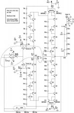
I'll be using BJTs in a 5-step cascode (See schematic)
The 2SC4686A's I'm using will work in the µA Range.
Last edited:
Here are a couple of threads that may be of interest to you,
http://www.diyaudio.com/forums/planars-exotics/72967-esl-headphone-direct-drive.html#post831791
and,
http://www.diyaudio.com/forums/head...discrete-class-headphone-amp.html#post2596223
This is the beginning to the previous link,
http://www.diyaudio.com/forums/head...discrete-class-headphone-amp.html#post2589794
I never went any farther than about 200v as I had other things that I had to do first.
But I did prove the concept by stacking about 4 or 5 FET's.
And I drove a Piezo element with two circuits in push pull.
It was quite loud and clean and I thought the element was going to crack but it didn't !!!
I have such circuits already drawn up and simulated in Circuitmaker for the 3KV to 5Kv range, But I just haven't got the parts to try them yet.
LTspice would be a good place to start for designing such a circuit as the whole stack could short and blow up losing a whole bunch of parts if not all of them in one instant.
All it would take is for one to go bad for a domino effect to occur.
I started at a lower voltage until I got the voltages stages balanced and equal then I brought the supply up another step and rechecked and adjusted everything until I got to 175v (160v to 180v).
My supply consisted of the same 25.2v radio shack transformer that I used to power my variable bias supply with a diode multiplier of 4 to 6 stages.
I don't remember exactly how many as it was about 5 years ago when I did it.
This was before I learned how constant current sources worked that is necessary in order to eliminate the costly power resistors by using FET's instead.
The use of load resistors is fine providing the current is low.
I have another schematic that I got from another forum that is along the lines of what you are trying to do and it uses a bunch of ZTX458's and ZTX558's stacked up and driven from a opamp on a +/- 800v supply and could be expanded very easily for higher voltages as well.
If it works as I would like to try it myself.
I will search for the JPEG and post it for you.
jer
- Status
- This old topic is closed. If you want to reopen this topic, contact a moderator using the "Report Post" button.
- Home
- Loudspeakers
- Planars & Exotics
- A Student's Attempt at the Plasmasonic Headphones.