hello
i spent last year building a prototype of an electromagnetic harp, as a part of my final thesis for music college.
the harp is basically an arduino controlled ebow harp, one custom built ebow for each string on the inside.

(sorry about the self image, linked to another site...)
there is atouch capacitance keyboard on a circular walnut case, and it can also run in a generative mode - creating its own music. i was really happy with the outcome...
here is an example of what it sounds like ::
electromagnetic harp test
ANYWAY
i plan on perfecting the instrument with a more powerful circuit, that doesn't distort the signal as much.
the LM386-4n in the ebow schematic i used doesn't make the strings vibrate until the chip basically outputting a nasty square wave. you can really hear the driver coil distortion through the resonance of the strings...
also, the response is terrible. i want each note to have a faster attack and more natural, clear sound to it. for that i need to design a NEW ebow circuit! one that is more clear and more powerful (more output to the 8ohm driver coils).
this is the one i used for the harp mentioned above ::
i was wondering if anyone here could help me out?
id like to avoid heatsinks, as i need to cram at least 26 amp circuits into a wooden box...!
is the TBA 820M perhaps a feasible option?
sorry about the long post, but i really hope someone can help me perfect this project!!! i want version 2.0 to rock your socks off!!!
all the best,
úlfur hansson
ulfurhansson.com
i spent last year building a prototype of an electromagnetic harp, as a part of my final thesis for music college.
the harp is basically an arduino controlled ebow harp, one custom built ebow for each string on the inside.
(sorry about the self image, linked to another site...)
there is atouch capacitance keyboard on a circular walnut case, and it can also run in a generative mode - creating its own music. i was really happy with the outcome...
here is an example of what it sounds like ::
electromagnetic harp test
ANYWAY
i plan on perfecting the instrument with a more powerful circuit, that doesn't distort the signal as much.
the LM386-4n in the ebow schematic i used doesn't make the strings vibrate until the chip basically outputting a nasty square wave. you can really hear the driver coil distortion through the resonance of the strings...
also, the response is terrible. i want each note to have a faster attack and more natural, clear sound to it. for that i need to design a NEW ebow circuit! one that is more clear and more powerful (more output to the 8ohm driver coils).
this is the one i used for the harp mentioned above ::
i was wondering if anyone here could help me out?
id like to avoid heatsinks, as i need to cram at least 26 amp circuits into a wooden box...!
is the TBA 820M perhaps a feasible option?
sorry about the long post, but i really hope someone can help me perfect this project!!! i want version 2.0 to rock your socks off!!!
all the best,
úlfur hansson
ulfurhansson.com
if you use linear amps there's little you can do to reduce power dissapation - you have to assume heatsinking of some sort is needed for more than a few W
the literaly cool way to drive is with Class D or PWM type drivers - requires external L,C - unless your driver has enough L of high enough Q
more detail about drive coil impednace, needed drive levels, frequency, would help
9 V battery power may just not do the job
the literaly cool way to drive is with Class D or PWM type drivers - requires external L,C - unless your driver has enough L of high enough Q
more detail about drive coil impednace, needed drive levels, frequency, would help
9 V battery power may just not do the job
the driver is a coil? - hand wound, or a standard part?
because you can change driver impedance by changing winding turns, wire gage, will act like a transformer to change the relation I,V to draw need power from a given supply V
you may want feedback gain control - digital pots are easily controlled by the uC
a modern implementation could use the ADC, PWM output of the uC, would need a level translator/buffer to get the I,V from the uC PWM drive - but then you need to master more subjects for the analog and digital control
Last edited:
hey jcx, this is very helpful...
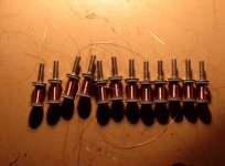
all the coils are hand woven... they look like this :
i didn't count the turns, as i used a power drill to wind them. they measure at 8 ohms.
perhaps they are covering to much space on the bobbin... would a coin shaped coil work better than a cigar shaped one?
all the coils are hand woven... they look like this :
An externally hosted image should be here but it was not working when we last tested it.
i didn't count the turns, as i used a power drill to wind them. they measure at 8 ohms.
perhaps they are covering to much space on the bobbin... would a coin shaped coil work better than a cigar shaped one?
can't tell how exactly those are made - AlNiCo core seems to be commonly used in the patent lit for the magnetic core to have some permability and DC field bias
Ebow Technical Analysis seems to be good for starting the patent search
good pickup design info http://web.archive.org/web/20110525.../phys498pom/498emi_guitar_pickup_results.html (original site down - go WaybBack Machine)
do you have an idea of the string motion range - how close the sustainer can be, or how big a gap if you use a more efficient magnetic core shape?
Attachments
Last edited:
- Status
- This old topic is closed. If you want to reopen this topic, contact a moderator using the "Report Post" button.
- Home
- Amplifiers
- Chip Amps
- creating my own instrument, need help with amp circuit!