Hi,
I´m trying to tweak a TASCAM MF-P01, this unit has 4 channel recording system in a single analog tape (using both sides A and B at once)
The matter is that the output is only stereo, and I need 4 channel independent output for digitalize the 4 channels at once with a computer...
The unit (as you can see) has 4 potentiometers, which will control the volume of each track for later mix them all into a stereo output for the listening..
Because I don´t have the schematics, I have put a cable into each potentiometer output with the hope of getting individual outputs with Line Level (10K output impedance, approx 1Vpp max) for multitrack digital recording.
Signal Volume at that point (potentiometer output) is around 100-150 mVpp max...
while line level output is at 1V-2Vpp max...
The idea is to use an LME49710 (or LM4562 Dual) for that, but I need orientation cause I´m quite lost in this...
What I know is that I need a preamp with:
- infinite impedance at his entry (for transparence to the rest of circuitry)
- gain of (1V/0.1V = 10 more or less)
- 10K ouput impedance for line level output (a resistor of course)
Can any expert iluminate this project? I mean how can I build the block system? one buffer followed by one amplifier? or maybe it can be done with only one IC?
any recommendation for circuity, IC types, etc?
any comment will be much appreciated!
Regards,
It sounds like you just need one gain stage per pot.
Recommends... I would go with an OPA2134 (dual FET opamp). This will eliminate any DC offset issues and it's one of the best sonically. It will also allow for direct connection to the pot wiper if needed without causing "noise" as the pot is turned, the FET opamp having essentially zero input bias currents.
So you need to be clear on what you want and what the set up is.
Vital info is...
Is the pot output (wiper) ground referenced with zero volts DC present or is it an AC coupled feed ?
Do you want the preamp to run on a single or dual rail ?
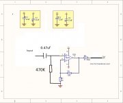
Each gain stage is text book stuff. Two resistors to set the gain keeping them in the 10K max region to minimise noise. A resistor of around 47 ohms in series with the output to isolate the opamp from capacitive loading that can give rise to instability. The input to the opamp at its most simple connects directly to the pot wiper if the feed is suitable. At its most complex it is isolated via a cap and the input pin of the opamp biased to ground (assuming a split supply) via a 470K or thereabouts resistor.
Recommends... I would go with an OPA2134 (dual FET opamp). This will eliminate any DC offset issues and it's one of the best sonically. It will also allow for direct connection to the pot wiper if needed without causing "noise" as the pot is turned, the FET opamp having essentially zero input bias currents.
So you need to be clear on what you want and what the set up is.
Vital info is...
Is the pot output (wiper) ground referenced with zero volts DC present or is it an AC coupled feed ?
Do you want the preamp to run on a single or dual rail ?
Each gain stage is text book stuff. Two resistors to set the gain keeping them in the 10K max region to minimise noise. A resistor of around 47 ohms in series with the output to isolate the opamp from capacitive loading that can give rise to instability. The input to the opamp at its most simple connects directly to the pot wiper if the feed is suitable. At its most complex it is isolated via a cap and the input pin of the opamp biased to ground (assuming a split supply) via a 470K or thereabouts resistor.
Yes, the pot is referenced with GND, I have thought to use a unity gain stage as a buffer and next to it a tipical amplifier Vo=(R2/R1)*Vin
The luck is that superquality is no needed, it´s only for digitalize old stuff (analog tapes), so I suppose there are more complicated circuits for better response, but for the moment I will test this easy configuration...
I suppose dual rail means to treat negative values (yes of course)
- I will keep in mind that R1=1K and R2=10K for example... that will be indeed sufficient low impedance for noise...
- 47 ohms resistor in series with the output... I need to put 10K for "Line Impedance" so I dont understand... do you mean to put 47 ohms in series with the 10k ohms? I will need the 10K in the output!
- The cap and 470K seems good idea...
- I will use caps next to the vcc and -vcc pins... and watch the signal In and out with a sine generator...
I´m trying now with a general pourpose tl082/tl072 it has low gain in high frequencies but for testing pourpose will be nice for later replace with OPA2134... what I´m wondering if it´s I can use only one stage (direct amplifier with very high impedance in it´s entry) thats why I use first a unity gain buffer first... tomorrow will post results...
thanks for the tips, building prototype right now...
Sorry for late reply.
The TL072/82 are absolutely fine for this at the gains you are using. The quality will be excellent. The OPA type opamps allow a lower impedance load to be fully driven such as 600 ohm.
The 47 ohm goes directly to the output pin and just ensures that whatever you hang on the end doesn't cause instability. Although you might be connecting to 10K load if the wiring/cable added a few 10's or hndreds of pf capacitance then that is waht can cause the trouble. The resistor stops it completely.
Quote
Vo=(R2/R1)*Vin
That sounds like the inverting configuration (not that it really matters for this)
The non inverting configuration is Vo=(R2/R1)+R1*Vin so you would need 9K and 1K for a true gain of exactly 10.
If you can say what power supply you have available eg whether its a single 12 volt or a dual -/+ 15 volt etc then we can advise better on the final configuration.
You are true about the output gain, Vo = (R2/R1) + R1 * Vin
I have attached a pdf with the basics of the circuit, including the 47 ohms at the output...
For transmission lines is good to have the same impedance in the output and the input... so if you have 10K load in the end of the wire it´s good to consider to put 10k in series in the beginning of the wire. Do you think that removing the 10K in series (in the output) would not be dangerous? the small capacitance due to the wiring lenght...would need 47 ohms or at least 47ohms? that´s why I have drawn two resistors in the output...
About filters...should I put 1uF in series in the output for removing DC Offset?
Is it then recommendable to put in the Input of the first AO a decoupling capacitor with 470K for removing glitches? testing now with TL072.. i have a bandwith with constant gain of 90 KHz so good good, the sound seems clear also...
All the Best
Attachments
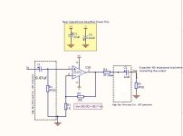
I've looked at your circuit and its basically fine theoretically.
In practice...
You don't need use two opamps. Just the second one is all you need.
Transmission lines really apply more to RF engineering than audio to ensure no power loss in transmission. The 10K resistor would actually cause a few problem. The output of a preamp is usually likened to a perfect voltage source, that is to say one that is unaffected by loading. The 10K resistor makes the circuit hugely dependant on what is connected to it. It could also cause premature HF roll off if any capacitance were present too. Also a 10 K resistive load would half the available voltage output.
DC offset isn't an issue with FET opamps but it would be with bjt types like the NE5532.
In the attached circuit the 0.47uF input cap ensures that you can connect the preamp to virtually anything.
It can be argued that the output should be AC coupled to in order to ensure total compatability to whatever you connect it too. If you know it will feed an input that is at zero volts DC nominally then there is no problem.
Attachments
Get it,
so wondering...
that cap with 470K its a high pass filter I suppose then that you remove any dc 0-10Hz from the input... that´s the only thing I see...
If I choose to put another cap in serie with R-47ohms in the output should I put also the 470K resistor to ground like the input? I suppose then that putting that filter in the ouput is to be protected from any dc level when connecting the recording device... ?
I need R1 for the gain equation to work! Vo=(R2/R1) + R1 * Vo I suppose that by mistake you have removed that resistor from the + input of the OA
Ah! Also I like the 47 ohms solution for protecting shortcircuits in the output connector hehe
I will remove then the 10K resistor... in power circuits for speakers I see it a lot for maximum power transfer but it´s true that here is no needed. Thanks again it´s almost done")
so wondering...
that cap with 470K its a high pass filter I suppose then that you remove any dc 0-10Hz from the input... that´s the only thing I see...
If I choose to put another cap in serie with R-47ohms in the output should I put also the 470K resistor to ground like the input? I suppose then that putting that filter in the ouput is to be protected from any dc level when connecting the recording device... ?
I need R1 for the gain equation to work! Vo=(R2/R1) + R1 * Vo I suppose that by mistake you have removed that resistor from the + input of the OA
Ah! Also I like the 47 ohms solution for protecting shortcircuits in the output connector hehe
I will remove then the 10K resistor... in power circuits for speakers I see it a lot for maximum power transfer but it´s true that here is no needed. Thanks again it´s almost done
Yes, the 0.47uf cap and 470K do form what is termed a "first order" high pass filter. The values ensure that the circuit passes all audio transparently and in fact the -3db point (voltage) is around 0.7 hz.
The 470 K also biases the opamp by providing a ground reference to the non inverting input pin. It also defines the input impedance. We normally make line inputs high impedance so that they don't load the circuit driving them. The noise contribution isn't an issue as it gets "shorted out" by the low impedance of the source driving the preamp.
If you wanted to put a cap in series with the output then its value would depend on the load impedance the amp has to drive. If we said 600 ohm minimum (which the TL072 won't drive fully) then to keep the "0.7hz -3db" would need around 400uf. That sounds way too large and in practice it is. Keeping to a more realistic 10hz -3db point and say 2K load which the TL072 can drive fully gives a much more reasonable 8uf. So in practice I would go for a 10 or even 22uf electrolytic (electros aren't all bad) if you feel you need for a cap at all.
A 470K (or lower) from the output end of the cap to ground is good practice because it defines a ground reference for the cap and ensures the output is at zero volts DC whether or not the amp is connected to anything.
R1 and the gain
I think I posted that before the circuit appeared and I was assuming R1 and R2 were the feedback components. So for the circuit above its
Vout = R3+R2/R3 *Vin which gives a gain of 11 of course.
Ouch!  "Never leave FET gates in open circuit"
The university told me thousands of times and yet I still forgotting that
While reading your reply I realize that the OA (because of his FETs) needs these protection of course! thats one of the 470K mission. Other way would be a cap to ground, but being carefully for high frecuencies attenuation... Good good, this is getting a very much clear project, again thanks a lot!
I think that with R1 I have mixed the previous inverting amplifier with the non-inverting one... ups!
ups!
EDIT: In the pdf I attached there are wrong values in C1 and C2 in fact C1=470nF and C2 ... C2 ... electrolitic 22uF?? but that is a polarized cap, we have a bipolar wave, mmm should I take 1uF tantalum better or put two caps of 22uF one for positive and the other for negative semicicles? What options we have?
When finished (I pretend to do it today or tomorrow) I will test it with the sine generator and oscilloscope, will post results
Cheers
"Never leave FET gates in open circuit"The university told me thousands of times and yet I still forgotting that
While reading your reply I realize that the OA (because of his FETs) needs these protection of course! thats one of the 470K mission. Other way would be a cap to ground, but being carefully for high frecuencies attenuation... Good good, this is getting a very much clear project, again thanks a lot!
I think that with R1 I have mixed the previous inverting amplifier with the non-inverting one...
ups!EDIT: In the pdf I attached there are wrong values in C1 and C2 in fact C1=470nF and C2 ... C2 ... electrolitic 22uF?? but that is a polarized cap, we have a bipolar wave, mmm should I take 1uF tantalum better or put two caps of 22uF one for positive and the other for negative semicicles? What options we have?
When finished (I pretend to do it today or tomorrow) I will test it with the sine generator and oscilloscope, will post results
Cheers
Attachments
Last edited:
The 470K actually biases the FET. Without a resistor here the FET input would be undefined at DC and so the voltage would be unpredictable and "roam" around. No DC current flows in the resistor but its vital it's there.
A 1uf ceramic is OK for the input but not perhaps the best choice quality wise. A film or polyester type would normally be used. That said the ceramic will work just fine.
The 470K resistor at the output needs to be on the other side of the cap. This always ensures the output is at zero volts DC.
The 22uf cap. An ordinary electroylitic is fine here because the AC signal changes equally on both sides of the cap and so the cap always sees 0 volts DC across it.
A practical point is that any minute DC offset at the opamp output could be "either way" (although unlikely there will be any with a FET opamp). So when the preamp is built and working and with NO signal measure the DC voltage across the 22uf cap. It should be no more than a mv or so and for perfection the cap should be orientated to alighn with the offset.
Attachments
Ok, very clear.
I understood the mission of C2, so in this case I can remove it because I´m using FETs...
What I feared is a DC offset coming from the other side connected to my OA Output, but... there is no sense in that point of course jaja
Then what I see is that I can remove R5 also and happily! cause when output is disconnected, the AO output current travels through R2 and R3 making the same function as R5... (the output will be tied to ground even without R5)
The FET opamp will give zero volts DC output so C2/R5 can be ommitted.
(having them present makes the design "universal" in that it would work under any scenario... if you know the conditions and what it connects to then they can be safely left out)
The opamp output is at a low impedance and settles to zero volts irrespective of R5 and irrespective of the values of the feedback network (although the feedback network determines the operating point... if that makes sense). Even a resistor from opamp output to either the plus or the minus rail would not alter the output voltage away from zero by even a mv (as long as the resistor didn't cause the opamp maximum specified output current to be exceeded).
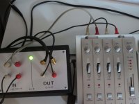
Ok, it´s done... and works like a charm!! 
Thank's Mooly it has been a very nice talk, I could make it and works better than the bipolar transistor of the main line output of the machine, because at 0dB (Attenuation of the fader) the signal is compressed and clips, while my TL081 +6V/-6V does not
So the differences viewed in SoundForge drops that this preamplifier is better than nothing inside the machine.. I recommend to anyone who has one of this old-school "thing" to build this one.
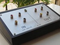
For that I have included the final schematic and the photo of the case...
I hope to be usefull for anyone making preamplifiers or even better for tweaking this old model of TASCAM
(Price of the components around 25 euros)
Best regards
Thank's Mooly it has been a very nice talk, I could make it and works better than the bipolar transistor of the main line output of the machine, because at 0dB (Attenuation of the fader) the signal is compressed and clips, while my TL081 +6V/-6V does not
So the differences viewed in SoundForge drops that this preamplifier is better than nothing inside the machine.. I recommend to anyone who has one of this old-school "thing" to build this one.
For that I have included the final schematic and the photo of the case...
I hope to be usefull for anyone making preamplifiers or even better for tweaking this old model of TASCAM
(Price of the components around 25 euros)
Best regards
Attachments
- Status
- This old topic is closed. If you want to reopen this topic, contact a moderator using the "Report Post" button.
- Home
- Source & Line
- Analog Line Level
- Need orientation with tweaking a TASCAM MF-P01