Hi !
Like I said in the thread "Board availability", I received my SSE PCB. It's from the new batch and I've some questions (I think George may/will be updating his website when less busy), so I made my thread...
a_ 2 diodes are added (D3 & D4) on PCB. Referring to http://www.diyaudio.com/forums/tubelab/210413-simplese-c1-value.html#post2978955, it seem to be 1N4007 diodes, like these 1N4007-T Diodes Inc | 1N4007DICT-ND | DigiKey . Am I right ?
b_ A place marked TR1 is also added, which semms to be a GE CL140. I don't see other components that could have be discussed in a thread...
c_ Two unused holes are under C22. What is their function ?
For the moment, I do not have any other component, but here is my purchase list :
- big CXSE25-8-5K Edcor OPT
- Edcor XPWR059 (750V (375-0-375) @ 175mA CT, 50V @ 50mA, 6.3V (3.15-0-3.15) @ 6A CT and 5V (2.5-0-2.5) @ 3A)
- Edcor choke
- Standard purchase list from Tubelab website
- KT88 tubes
- maybe no SS rectifier
- A cathode bias resistor switch (rotary or toggle, don't know yet)
I will take my time (I'm pretty busy (work, familly, ...). moreover, Edcor order is about 400$ , I'll wait few months to save money...
It's gonna be a really nice project !
Like I said in the thread "Board availability", I received my SSE PCB. It's from the new batch and I've some questions (I think George may/will be updating his website when less busy), so I made my thread...
a_ 2 diodes are added (D3 & D4) on PCB. Referring to http://www.diyaudio.com/forums/tubelab/210413-simplese-c1-value.html#post2978955, it seem to be 1N4007 diodes, like these 1N4007-T Diodes Inc | 1N4007DICT-ND | DigiKey . Am I right ?
b_ A place marked TR1 is also added, which semms to be a GE CL140. I don't see other components that could have be discussed in a thread...
c_ Two unused holes are under C22. What is their function ?
For the moment, I do not have any other component, but here is my purchase list :
- big CXSE25-8-5K Edcor OPT
- Edcor XPWR059 (750V (375-0-375) @ 175mA CT, 50V @ 50mA, 6.3V (3.15-0-3.15) @ 6A CT and 5V (2.5-0-2.5) @ 3A)
- Edcor choke
- Standard purchase list from Tubelab website
- KT88 tubes
- maybe no SS rectifier
- A cathode bias resistor switch (rotary or toggle, don't know yet)
I will take my time (I'm pretty busy (work, familly, ...). moreover, Edcor order is about 400$
, I'll wait few months to save money...It's gonna be a really nice project !
Last edited:
There are 3 new components on the new board. If you really want your board to be exactly like the old board all 3 can simply be replaced by a jumber wire made from a resistor lead.
D3 and D4 are indeed 1N4007. I suppose a purist will use an UF4007 but it shouldn't make any difference since the rectifier tubes characteristics dominate.
TR1 is a GE CL140.
All 3 or these components were added to make life easier on the rectifier tube under start up conditions. Many of the current production tubes aren't built like the old ones were.
You may find that 47uF 500V electrolytics are hard to find. 56uF's seem to be available, yet this is above the reccomended limit for a 5AR4. I am testing the 56 uF with several dozen 5AR4's and the 3 added parts before recommending this though.
The 2 unused holes near C22 are for connecting the circuit from one side of the board to the other. No components are placed in those holes. These "extra" holes have been in all SSE boards made.
These boards use plated through holes. This means that there are copper circuit traces in ALL of the holes. Many of the holes used for component leads are also used for top to bottom connection. Do NOT drill the holes out to fit a fatter component lead.
There has been exactly ONE SSE that didn't work and couldn't be fixed on this forum. I had the builder send it to me and found that he had drilled the coupling cap holes larger to fit some really big caps with really fat wires. This killed the connection, and broke the amp. The cure is to solder the component to the board on both sides so that the component lead completes the connection.
Thanks George for this detailed answer.
Thread about C1 value mentions 33µF, which logically seems better for the tube.You may find that 47uF 500V electrolytics are hard to find. 56uF's seem to be available, yet this is above the reccomended limit for a 5AR4. I am testing the 56 uF with several dozen 5AR4's and the 3 added parts before recommending this though.
Yep, I saw that in 1 or 2 threads, for example : http://www.diyaudio.com/forums/tubelab/186433-r3-soldering-pad-ruined.html#post2560571These boards use plated through holes. This means that there are copper circuit traces in ALL of the holes. Many of the holes used for component leads are also used for top to bottom connection. Do NOT drill the holes out to fit a fatter component lead.
There has been exactly ONE SSE that didn't work and couldn't be fixed on this forum. I had the builder send it to me and found that he had drilled the coupling cap holes larger to fit some really big caps with really fat wires. This killed the connection, and broke the amp. The cure is to solder the component to the board on both sides so that the component lead completes the connection.
Thanks George for this detailed answer.
Thread about C1 value mentions 33µF, which logically seems better for the tube.
I would go with less than 47 uF for c1 unless you plan on buying a NOS 5AR4, the new ones will eventually arc over and fail. When I first built my SSE I also had a preamp with a 5AR4, and I had a Sovtek and a JJ go out on me. After purchasing a few NOS tubes I went the next 4-5 years with no problems. The diodes added probably save the new 5AR4s, as they can't seem to perform up to spec. You can get a 47 uF 500V JJ cap from partsconnexion.
Hi all !
I'm updating this post !
I'm starting soldering, even if I'm lacking R14/ R24 (10K 3W) and R2 (150K 3W), and the GE CL-140.
In BOM, these resistors are metal film oxyde, is it ok if I order carbon film resistors ?
I just have another question : what is the approximative length of Edcor transformers wires?
Thanks !
Hi all !
I'm updating this post !
I'm starting soldering, even if I'm lacking R14/ R24 (10K 3W) and R2 (150K 3W), and the GE CL-140.
In BOM, these resistors are metal film oxyde, is it ok if I order carbon film resistors ?!
As long as they have the right power rating, they will work fine.
these are not shown on the schematic? how can they be added to the old design?
There is no provision on the old PC board for these parts. It is easy to do off board, and I explained how in a thread somewhere.
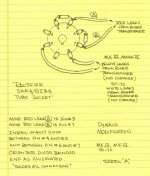
You can add the diodes by soldering the anode of a diode to the end of each red wire on the power transformer and covering it with heat shrink tubing. The stripe (cathode) on the diode is the free end. It is inserted into the terminal strip on the PC board where the red wires were.
You can solder the CL-140 to the power transformers red/yellow wire and insert the other end into the boards terminal for the red/yellow wire. The CL140 has no polarity.
Both of these additions are for improving the reliability of the 5AR4 tube and do not affect the sonics of the amp. Ordinary 1N4007 diodes work fine since the characteristics of the tube rectifier prevail, but you can use fast rectifiers (FR4007) or other exotics as long as they are rated for at least 1000 volts and 1 amp.
Thanks Russ and George for additionnal information. Do you know an equivalent for GE CL-140, but from EPCOS ?
I'm lost in specs, and I don't really know which is a real requirement... Moreover, GE thermistors are in stock in USA and shipping is $18+...
For resistors, I thought about inductive, or other disturbing effects, but if carbon film resistors are OK, no problem
I'm lost in specs, and I don't really know which is a real requirement... Moreover, GE thermistors are in stock in USA and shipping is $18+...
For resistors, I thought about inductive, or other disturbing effects, but if carbon film resistors are OK, no problem
Hi !
my purchase list :
- big CXSE25-8-5K Edcor OPT
- Edcor XPWR059 (750V (375-0-375) @ 175mA CT, 50V @ 50mA, 6.3V (3.15-0-3.15) @ 6A CT and 5V (2.5-0-2.5) @ 3A)
!
Hi, i am new here as well and i don't understand;
1. do i need 6.3v CT or just 6.3v
2. How much amper is to much? 6A, 8A
3. I bought 300b psvane how much voltage can i put on it?
4. Is Edcor XPWR032 (voltage windings, 800V (400-0-400) at 150mA center tapped, 12.6V at 600mA, 6.3V at 4A and 5V at 3A ) Ok?
Thanks you all,
Ran
I'm going to assume that you have a Tubelab SE and not the SSE.
1) CT on 6.3VAC is not required for SE if you are running 300Bs. It is required if you plan to run 45s.
2) 4A is the recommended minimum for 6.3V when using 300Bs. Less for 45s, more for 2A3.
3) George's recommendations for the 300B setup will give you around 350V on the 300Bs. I can't speak about the psvane, specifically.
4) That will give you way too much B+ for 300Bs.
You can put 450V on the Psvanes. Increase the current in the 5842 so you can adjust down the voltage, since B+ will be higher.
thanks to all,
Cotdt ,
1. did you wrote this from your own experience or common knowledge?
2. you mean the 5842 plate voltage?
I must say thanks to George that beacuse of his great site i found a new hobby
p.s.
Do someone know were can i get the "Single Ended Amp Cad" program?
(it's out of stock in "Antique Electronic Supply")
quinnling, as long as i know GlassWare Programs send you to "Antique Electronic Supply" to buy the CD.
and they don't have it in stock.
and they don't have it in stock.
I would go with less than 47 uF for c1 unless you plan on buying a NOS 5AR4, the new ones will eventually arc over and fail. .
I bought 2 of these, with 1 in my SSE; they behave electrically just as 5AR4s.
5AR4 Rectifier Tube Mil Philips Mislabeled 5V4GA | eBay
Also, Eli Duttman posted this schematic for new production 5AR4s for keeping them alive
Attachments
- Status
- This old topic is closed. If you want to reopen this topic, contact a moderator using the "Report Post" button.
- Home
- More Vendors...
- Tubelab
- Starting a SSE build