I would like to eliminate the electrolytic cathode bypass caps and try a different way to bias my amplifier, it's a Tubelab SSE with 12BH7A driver tube and EL34 power tubes running in triode mode with no feedback. Currently, the cathode bias is set up as shown in the schematic, linked below:
Simple SE schematic
I would appreciate any suggestions! A loss of 6-9 dB in gain is ok, and would be welcome.
Simple SE schematic
I would appreciate any suggestions! A loss of 6-9 dB in gain is ok, and would be welcome.
I would like to eliminate the electrolytic cathode bypass caps and try a different way to bias my amplifier, it's a Tubelab SSE with 12BH7A driver tube and EL34 power tubes running in triode mode with no feedback. Currently, the cathode bias is set up as shown in the schematic, linked below:
Simple SE schematic
I would appreciate any suggestions! A loss of 6-9 dB in gain is ok, and would be welcome.
I think yo might lose some low frequency too, if you remove the cathode bias cap.
I think you can reduce the value "some." The existing is 1500uF and that can be reduced. But you may not be able to eliminate a bypass entirely, just from the standpoint of low frequency roll off.
I think you can make the gain less by changing the plate resistor.
(link)
Cathode Bypass Capacitor Calculator
You see with a 1500 uF bypass, you are well down to below 20 Hz,
With a 22 uF bypass, you are rolling off at about 100 Hz, and 20 Hz is gone.
In this set up, a voltage regulator is used to supply voltage to the plate
resistor, and I am thinking that by adjusting the gate voltage from R19,
you might be able to adjust the gain of the thing...maybe I'm wrong but
it looks that way.
Last edited:
The best way to do this in the driver stage - and what I've done myself - is to use a DHT in filament bias. This requires some knowledge, but isn't complex though it does require a DC filament supply to each DHT. You'd have to change your amp - add stuff and make an additional hole for a second tube in the driver stage.
My driver stage is a 4P1L (mu=10) which would give you about the gain you desire. I run it into a Hammond 126C interstage but a 126B may be better. Cathode resistor is 20 ohms so no need to bypass. 165v on the plate, 15v supply to the filaments in filament bias, so this feeds the filament and cathode resistor in series and the resistor sets the bias.
I loathe cathode bypass caps - they kill the sound and make it bland. Electrolytics are worst but polypropylene aren't that good either, in fact I don't want caps anywhere near the signal path. I tolerate a cathode bypass of the output stage, but these days I use PP amps anyway so use CCS and pentode sinks under the diff pairs.
andy

The best way to do this in the driver stage - and what I've done myself - is to use a DHT in filament bias. This requires some knowledge, but isn't complex though it does require a DC filament supply to each DHT. You'd have to change your amp - add stuff and make an additional hole for a second tube in the driver stage.
My driver stage is a 4P1L (mu=10) which would give you about the gain you desire. I run it into a Hammond 126C interstage but a 126B may be better. Cathode resistor is 20 ohms so no need to bypass. 165v on the plate, 15v supply to the filaments in filament bias, so this feeds the filament and cathode resistor in series and the resistor sets the bias.
I loathe cathode bypass caps - they kill the sound and make it bland. Electrolytics are worst but polypropylene aren't that good either, in fact I don't want caps anywhere near the signal path. I tolerate a cathode bypass of the output stage, but these days I use PP amps anyway so use CCS and pentode sinks under the diff pairs.
andy
Thanks, if you have a schematic for the driver stage you are talking about I'd love to see it. Also for the PP amp, I am already thinking of an amp that will top the SSE, but I'm also interested in modifying the SSE... so far by bypassing the el34's cathode caps and replacing the last electrolytic in the ps with a 100 uF film cap. Next big thing in my system is looking like a hirez usb dac, my current dac is 20 years old.
1) LED Bias
2) Fixed Bias
Thanks, is the sound of LED biasing better than a resistor/cap?
Also, the driver stage has a CCS loaded anode, so if the cathode cap isn't there the CCS will just push the ac through the resistor, would the driver stage work without any cathode cap at all, that is without rolling off bass freqs?
Cathode bias with resistor/cap provides feedback by DC current, so current through the tube stays stable. If you eliminate it you need to take care of bias. No free lunch. The best way of course is to ground cathode and provide a negative bias voltage on the first grid from additional voltage source. Adjusting this voltage you can adjust tube current. However you can achieve similar result using Zeners, or diodes, or LEDs, in cathode, but you can't adjust bias such a way.
Cathode bias with resistor/cap provides feedback by DC current, so current through the tube stays stable. If you eliminate it you need to take care of bias. No free lunch.
I was wondering, since the driver tube's anode is ccs loaded, if it would be possible to get rid of the cathode cap in the driver stage as the ccs would stabilize the current?
Going back to filament bias - I think this is the "free lunch". No input cap that you'd have with battery grid bias, and a cathode resistor that doesn't need to be bypassed. I'd prefer the sound of a good 20 ohm wirewound resistor (needs to be as good as possible - I use 20W DALE surplus stock off ebay). I've compared all these options - including LEDs etc in the cathode - and to my ears a properly executed filament bias is my preferred sound.
It's unconventional and there are only a few tubes you can use comfortably at lower voltages but these include the 26 and 4P1L, which is enough for me. Basically for a driver stage you need a bias voltage of up to 15v and a low filament voltage ( 26 = 1.5v, 4P1L = 2.1v) to get away with a supply voltage of around 20-24v into a filament board such as Rod Coleman's. For a preamp, you can use a supply of as little as 12v and a bias voltage of more like 4-5v. Easy stuff - I've even used a standard DC 12v mains supply! Choke input is even better - the supply really needs to be uber-clean. But satisfy these conditions, and in my view you have your "free lunch".
Andy
Last edited:
Hi!
The simplest way to bypass the signal around the cathode cap is the ultrapath connection from B+ to cathode. In same cases (depends on transformer and tube) the cathode bypass cap can even be completely omitted. The only drawback is the need for a very ripple free B+
Best regards
Thomas
The simplest way to bypass the signal around the cathode cap is the ultrapath connection from B+ to cathode. In same cases (depends on transformer and tube) the cathode bypass cap can even be completely omitted. The only drawback is the need for a very ripple free B+
Best regards
Thomas
I was wondering, since the driver tube's anode is ccs loaded, if it would be possible to get rid of the cathode cap in the driver stage as the ccs would stabilize the current?
You can take the cathode electrolytics away without any effect to frequency response or DC-bias, and since your anode has a CCS loading the gain will be reduced very little too.
Hi Dave,
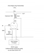
You asked for a picture of the 4P1L in filament bias, and here's a roughly drawn one for you!
I haven't tried the 126B. That's rated 30mA, but only 44H inductance. 126C is rated 15mA and 105H. For a driver stage the 4P1L could be run at around 20mA or even up to 25mA.
andy
You asked for a picture of the 4P1L in filament bias, and here's a roughly drawn one for you!
I haven't tried the 126B. That's rated 30mA, but only 44H inductance. 126C is rated 15mA and 105H. For a driver stage the 4P1L could be run at around 20mA or even up to 25mA.
andy
Attachments
Last edited:
You can take the cathode electrolytics away without any effect to frequency response or DC-bias, and since your anode has a CCS loading the gain will be reduced very little too.
Yes, easiest thing to do - unsolder one connection to the bypass cap. Put in a temporary switch if you like to do A/B.
More advanced option, for fun (ala Wavebourn), is to convert the ccs to a gyrator (fixed anode voltage, but high impedance at audio frequencies). This allows the current to adjust as the tube ages, just as it would with cathode bias.
Sheldon
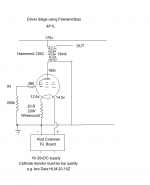
Ammended version - the 4P1L is used in triode mode with grids 2+3 connected to plate (pins 2+3+4). Filaments are wired in parallel (1+7 and 8)
Andy
Thanks! This looks interesting, I will look into it... maybe for my next amp and not the SSE though. I think I will start with removing the cathode cap in the driver stage of my SSE, that's a simple enough mod.

Its the funniest thing...
Everyone talks about caps as if they are the culprits in "the sound" (problem). After much esquisitely precise testing ... I have found that the "cathode cap" is not in itself the "problem", but rather tightly controlled fixed bias (which is what a resitor + capacitor makes). In essence, the resistor and capacitor form a tiny, compact power supply in series with the cathode, raising its voltage relative to the grounded grid. To all the well-informed here, this is nothing at all new, or even "newly revealed". It just is.
For instance ... so long as one's using a separate winding of the transformer for filament power, it is pretty straight forward to make a low current negative power supply ... a few rectifiers, capacitors, a very low current choke, and so on ... With nothing more sophisticated than a quality pot, one can get 0 to -15 volts of bias for the grid. Grids just aren't connected by a high-value resistor to round, but rather, to the wiper of the pot sitting across ground and the C- supply.
The effect of this kind of supply is exactly the same as using a cathode-resistor-and-capacitor (of sufficiently high quality capacitor and low-value low-impedance double-bypass caps, of course). Using a DPDT switch and careful calibration of the ampere flow through the cathode ... one can do A/B comparison trivially. Amplification remains a constant. Whatever "problem" the fixed bias has given the system, remains in both cases.
Not so... when one uses the bias-in-cathode resistor WITHOUT the capacitor. Now suddenly the tube will behave much less like a Gm (transconductance) amplifier, and more like a cathode follower (with multiplicative gain on the anode load). Almost all nonlinearities that the transconductance-as-a-function-of-current curve produces with fixed bias are removed. Not all, must most. In simple circuits without fancy constant-current or cascode loads, the net effect is reduced gain and increased linearity. It is hard to do the "a/b" switch ... requires a 3PDT switch to do it right and an OUTPUT pot to reduce gain from the cap-bypassed higher-gain configuration. Doable, but not easy. The sonic difference though is quite remarkable. "Floating bias" (or loosely, cathode-follower) response is more linear - but the effect seems to also be a slight muffling of the sound. Overall - when the whole system gain is pepped up just a bit to accomodate that ... the sound becomes lovely and more rich due to increased symmetric linearity.
So... there you are. Stuff wrought from hundreds of hours of fiddling.
GoatGuy
- Status
- This old topic is closed. If you want to reopen this topic, contact a moderator using the "Report Post" button.
- Home
- Amplifiers
- Tubes / Valves
- Eliminating Cathode Bypass Caps In SET Amplifier