After a few years of on-off again interest in diy audio, I finally got round to actually building something. I was inspired by the Zen V5 and later by the F5. I wondered if I could perhaps marry some of the ideas there with something I always wanted to try - transformer coupled inputs doing some of the voltage gain duties feeding a fet in common source configuration.
Some searches basically yielded some interesting topologies with pretty good results (see the Zeus Amp, Tubecad, ciuffolis Circlotron). So that gave some comfort that this wasn’t a completely barmy idea. I got some great ideas and insights here too: http://www.diyaudio.com/forums/solid-state/24744-push-pull-using-only-n-channel-mosfets.html
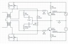
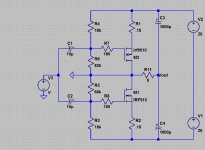
So I wondered if we could get measured performance somewhere between a ZV5 and F5 with respect to THD, bandwidth and low output impedance. Much ruminating, reflection and reading yielded two or three ways of slapping on a tx front end to a ZV5 and I settled on this one:
p.s i'm not too good with schema software so used circuitlab an online thing - sorry for the poor layout but its manual. also watch out for the wrong mosfet symbol - I have noted it in the schema..[EDIT: Phase for top secondary winding is shown incorrectly, it needs to be flipped] if anyone can do a better one to aid discussion that would be great!
Some searches basically yielded some interesting topologies with pretty good results (see the Zeus Amp, Tubecad, ciuffolis Circlotron). So that gave some comfort that this wasn’t a completely barmy idea. I got some great ideas and insights here too: http://www.diyaudio.com/forums/solid-state/24744-push-pull-using-only-n-channel-mosfets.html
So I wondered if we could get measured performance somewhere between a ZV5 and F5 with respect to THD, bandwidth and low output impedance. Much ruminating, reflection and reading yielded two or three ways of slapping on a tx front end to a ZV5 and I settled on this one:
p.s i'm not too good with schema software so used circuitlab an online thing - sorry for the poor layout but its manual. also watch out for the wrong mosfet symbol - I have noted it in the schema..[EDIT: Phase for top secondary winding is shown incorrectly, it needs to be flipped] if anyone can do a better one to aid discussion that would be great!
Attachments
Last edited:
Some details..
Mosfets: I tried the 2sk1058/2sj162 laterals and the IRF240/9240 as well. Six mosfets were killed during the making of this movie (well so far..)
In the end I settled on the laterals because I just found I didn’t have to work so hard stabilizing bias but will go back to the IRF parts at some point once I have decent heatsinking in place.
Input transformers:
I bought and tested quite a few power transformers. I took a look at the audio types but the ones with wide quoted bandwidth were pretty expensive and so I left that as a possible future upgrade. In general, toroids were far better than EI types. A local cheap n cheerful one seemed to work fine so I went ahead and ordered a few types from Digikey to check results so that others could try it as well if they liked. The one I used for testing was a 50VA VPT24-2080 from Triad Magnetics ($16.45 from digikey). There are plenty more on my bench and I'll report back later on results in the amp. In general though, it looked like you needed a decent size (I tried 2va and 5va and didn’t get very good results), dual split primaries (which I'd use as secondaries) and the rights turns ratio (2x 12 volt secondaries, 2x115V primaries) - and we're in business. Since the transformer is outside the FB loop so any response anomalies or bandwidth restrictions aren't addressed by the amp. Wideband/broadcast quality audio coupling transformers run north of $100 bucks and perhaps worth the dough once the basic topology is proven. 600 ohm/10k impedance seem the type I'd want if I went down this route....
Results (so far .. need help to improve..)
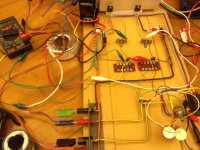
This is a bench-test only but initial results seem ok. After frying so many fets, I didn’t want to drive things too hard so just settled on 850mA bias and 20v rails.I didn't take the o/p beyond 14.5V pk-pk this round. Test load was 6.8 ohms, so I guess that equates to 15W or so (only the first third of which is in class A at this stage due to the bias). That is if I got my math right!
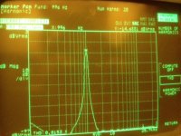
Initial measurements results at 14.5V Pk-pk into 6.8R resistive load:
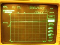
Bandwidth: +/- 0.5db 5Hz to 40kHz.
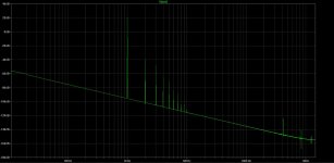
THD (20) 1kHz: 0.0144%
THD (20) 10kHz: 0.051%
Gain was ca 15x closed loop and approx 50+ open loop. The open loop gain was roughly in line with calcs assuming Gm of 1S into 8 ohms irc...
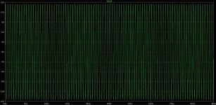
Distortion spectrum is largely 2nd harmonic. The measurements were made with my cranky 35665a DSA... if any suggestions on how to improve my measurement technique with this machine please let me know - what I have is just from learning through trial and error!
I haven’t made any special efforts at optimizing apart from choosing the feedback resistor value. The tx secondary needs to be loaded with a high value R to reduce the slight gain at HF, and perhaps some multiple parallel mosfets might help load it a bit too")
Output impedance was a disappointing 2.3R ... this is something I really hope to be able to reduce down to 0.5R or so if I can.
This is a bench-test only but initial results seem ok. After frying so many fets, I didn’t want to drive things too hard so just settled on 850mA bias and 20v rails.I didn't take the o/p beyond 14.5V pk-pk this round. Test load was 6.8 ohms, so I guess that equates to 15W or so (only the first third of which is in class A at this stage due to the bias). That is if I got my math right!
Initial measurements results at 14.5V Pk-pk into 6.8R resistive load:
Bandwidth: +/- 0.5db 5Hz to 40kHz.
THD (20) 1kHz: 0.0144%
THD (20) 10kHz: 0.051%
Gain was ca 15x closed loop and approx 50+ open loop. The open loop gain was roughly in line with calcs assuming Gm of 1S into 8 ohms irc...
Distortion spectrum is largely 2nd harmonic. The measurements were made with my cranky 35665a DSA... if any suggestions on how to improve my measurement technique with this machine please let me know - what I have is just from learning through trial and error!
I haven’t made any special efforts at optimizing apart from choosing the feedback resistor value. The tx secondary needs to be loaded with a high value R to reduce the slight gain at HF, and perhaps some multiple parallel mosfets might help load it a bit too
Output impedance was a disappointing 2.3R ... this is something I really hope to be able to reduce down to 0.5R or so if I can.
Attachments
Last edited:
sooo... i was *hoping* to get some input/suggestions/feedback on the project and any tips would be welcome. In particular though, I have a few questions at this stage:
a) ZV4 Biasing arrangement: Why do we take the bottom leg of the bias resistor network to the drains i/o ground ? It works both ways, but there must be some benefit of doing so but I'm not sure I understand what it is. Taking it off the amp outputs means that there is some feedback here as well - so is that the only benefit ? But you cannot vary the feedback in this config without also varying the bias so this seems a little superfluous since I have a separate feedback loop ?
b) This amp feedback arrangement: I tried and tried and tried to think of ways I could get rid of that DC blocking cap in the f/b loop but cannot (and no i don't want to move it to the input drives .
With the current feedback resistor chosen, you cannot see it, but at some higher levels of feedback, I get weird freq response (within +/- 0.5 to 1db but just looks strange). I guess I can live with this since the practical results seem decent enough to warrant tweaking and listening but this also means I cannot just vary fb with a free mind as I try to get a lower output R.
c) If i cant mess with the feedback, any other suggestions to lower output impedance significantly - i can only think of more o/p devices and maybe lower the 0.47ohm resistors. not sure if the latter makes that much diff if i had a properly set up fb network ...
If anyone wants to try this or has questions, feel free to shoot.... I'm travelling the next few days so no soldering iron time, but I thought the time might help with, you know, reflections and discussion... thanks in advance for the help and most of all to NP for his wonderful, inspiring articles and projects....
a) ZV4 Biasing arrangement: Why do we take the bottom leg of the bias resistor network to the drains i/o ground ? It works both ways, but there must be some benefit of doing so but I'm not sure I understand what it is. Taking it off the amp outputs means that there is some feedback here as well - so is that the only benefit ? But you cannot vary the feedback in this config without also varying the bias so this seems a little superfluous since I have a separate feedback loop ?
b) This amp feedback arrangement: I tried and tried and tried to think of ways I could get rid of that DC blocking cap in the f/b loop but cannot (and no i don't want to move it to the input drives
. With the current feedback resistor chosen, you cannot see it, but at some higher levels of feedback, I get weird freq response (within +/- 0.5 to 1db but just looks strange). I guess I can live with this since the practical results seem decent enough to warrant tweaking and listening but this also means I cannot just vary fb with a free mind as I try to get a lower output R.
c) If i cant mess with the feedback, any other suggestions to lower output impedance significantly - i can only think of more o/p devices and maybe lower the 0.47ohm resistors. not sure if the latter makes that much diff if i had a properly set up fb network ...
If anyone wants to try this or has questions, feel free to shoot.... I'm travelling the next few days so no soldering iron time, but I thought the time might help with, you know, reflections and discussion... thanks in advance for the help and most of all to NP for his wonderful, inspiring articles and projects....
Just a note that the THD measurements and screenshots in post #4 are just plain wrong! Looking at the amplitude makes it obvious I guess (well only in hindsight!) ... Freq response is right though ....got a tonne of ideas and insipirations from the F6 thread (and leads from there as well) so I'll fire up the iron again tonight and see what happens !
Output impedance was a disappointing 2.3R ... this is something I really hope to be able to reduce down to 0.5R or so if I can.
do not be disapointing, this is V to I converter amp, it has to have high output impedance.
I can bet that the sound is incredible, all you have to do is flatten with RC filters impedance peaks inside your speakers like this Project CS-8 - Current-Drive - The Natural Way of Loudspeaker Operation
or
or use inerted follower like this
and
what is great
you can screw M1,2 directly to the heatsink without isolation
to prevent thermal runaway use VBE multiplier or diodes is a must
of course the input tr should have "voltage gain"
cheers!
PS wow, the 8th, 9th and the rest harmonics bellow -100dB with +-15VAC!!! must sound incredible, please play with ltspice file
You can try using feedback to the primary like in
the F6 if you want to lower the output impedance
or use inerted follower like this
and
what is great
you can screw M1,2 directly to the heatsink without isolation
to prevent thermal runaway use VBE multiplier or diodes is a must
of course the input tr should have "voltage gain"
cheers!
PS wow, the 8th, 9th and the rest harmonics bellow -100dB with +-15VAC!!! must sound incredible, please play with ltspice file
Attachments
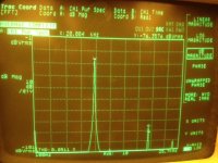
cool thanks ! ... if youre referring to my thd results in post #4, just wanted to repeat that they are incorrect corrected measurements with the secondary feedback loop disabled (ie no R9, R10 and no caps) give me 0.27% thd (mostly low order stuff) @ 15v pk-pk and touches 1% THD @ 32 V pk -pk ...
not too shabby for such a simple circuit for 1% to come in at 75 W RMS into 6.8 Ohm load and 24V rails ... driving the sucker is a different problem though so I may have shifted the hassles downstream, but yes it does sound lovely so far!
I will try the follower design once I have exhausted what i can do here ... thanks matey
corrected measurements with the secondary feedback loop disabled (ie no R9, R10 and no caps) give me 0.27% thd (mostly low order stuff) @ 15v pk-pk and touches 1% THD @ 32 V pk -pk ... not too shabby for such a simple circuit
for 1% to come in at 75 W RMS into 6.8 Ohm load and 24V rails ... driving the sucker is a different problem though so I may have shifted the hassles downstream, but yes it does sound lovely so far!I will try the follower design once I have exhausted what i can do here ... thanks matey

or use inerted follower like this
and
what is great
you can screw M1,2 directly to the heatsink without isolation
to prevent thermal runaway use VBE multiplier or diodes is a must
of course the input tr should have "voltage gain"
cheers!
PS wow, the 8th, 9th and the rest harmonics bellow -100dB with +-15VAC!!! must sound incredible, please play with ltspice file
Why is there a wire (dead short) between output and ground in the shown schematic?
Why is there a wire (dead short) between output and ground in the shown schematic?
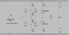
it is inverted style source follower pp, the output is taken from the sources, not the drains
Oops, I missed that when I first looked at the schematic. Other than in circlotrons, I haven't seen the power supplies floated like that.it is inverted style source follower pp, the output is taken from the sources, not the drains
Ok, so I just went ahead and built the schematic in post #11. I used IRF510 and IRF9510. No transformer input. Schematic below. I changed some of the resistor values based on what I had and added the two caps because I couldn't figure out how to hook up the speaker without them. I admit it, I got a lot to learn. I used a capacitance multiplier power supply that I've built for an upcoming JLH build. I started with about +-10v and ran up the volume. Out came music. Sounded pretty good. Fets started to get warm so I shut it down, screwed them to a heatsink and tried again. This time +- 12v. Again, music sounding good. I started to worry about thermal runaway (which I got from the padamiecki post) so I shut it down. That's where I stopped. Now I need to figure out how to implement Vbe multiplier or diodes like padamiecki recommends. It did sound good though.
Tom
Tom
Attachments
- Status
- This old topic is closed. If you want to reopen this topic, contact a moderator using the "Report Post" button.
- Home
- Amplifiers
- Pass Labs
- Ticle Zen Amp