Hello,
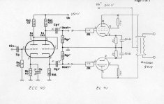
After a lot of studying I tried to build my first push-pull amplifier, making use of an ECC40 as phase inverter and EL41 as output tubes, and a UNITRAN 9U14 output transformer.
I "designed"my own schematic, according to the "copy and paste" method, and using a conventional EZ81 power supply, using a 10H 200mA choke.
The result: output tubes become VERY hot and a lot of hum, bad sound.
Obviously I did something wrong.
Can anyone help me out and check this schematic?
Harm
Attachments
they are not that scarce.
I beleive a certain datasheet lists them as an EL84 equivalent whilst they are not.
the EL84 however does share the bias setting of -7v Vg1 for class A the autobias resistor for 36 and respectively 44Ma will mean the EL41 will Bias significantly Hotter in a circuit designed for a 84
I have always wondered if it weren't possible to Bias output tubes whit a decent wattage zener diode . just like led bias. in this configuration matching tubes for Idle current draw would be easy.
have a nice day.
v4lve
Hi,
To me your circuit looks somewhat strange:
1)
Cathode-resistors of the EL-41 are 150 Ohm, each according to the EL41 data-sheet available here:
----> http://www.r-type.org/pdfs/el41.pdf
That should put your EL's in a safe operating zone.
2)
Coupling cap's from the Phase-Inverter are 10nF. I would suggest 470nf ~ 680nF unless you don't want any bass.
3)
Phase-Inverter Cathode & Anode resistors are way too big. 22K ~ 47K seems more appropriate.
4)
With the rather low anode-supply you have for the Phase-Inverter you'll find it hard to set the operating point suitable for the required output (~13,5VRMS). Go with a self-biased, AC-coupled Phase-Inverter, it's much easier to control if you're no pro (like me") )
)
5)
Triode-coupled EL41? OK, that'll give you at the max. 4W output. Fine, if you have the speakers to match it. Connecting the Screen-grids through a 1KOhm resistor directly to the B+ (300V) supply will give you 3 times as much output.
6)
No NFB? It may still sound OK. Hard to say without trying. To lower the Zout and thereby shaping-up bass performance besides reducing distortion I would go with NFB. It's easy to implement: Put a 100R resistor in series with RK(I) ground-end and connect a 10K trimpot between the junction and the hot 8-Ohm speaker terminal. The cold speaker terminal should be connected to ground.
If you experience self-oscillation, reverse the EL41 anode transformer connections.
Adjust the pot for best performance and suitable amplifier sensitivity. Applying more NFB = less sensitivity.
rgds,
/tri-comp
To me your circuit looks somewhat strange:
1)
Cathode-resistors of the EL-41 are 150 Ohm, each according to the EL41 data-sheet available here:
----> http://www.r-type.org/pdfs/el41.pdf
That should put your EL's in a safe operating zone.
2)
Coupling cap's from the Phase-Inverter are 10nF. I would suggest 470nf ~ 680nF unless you don't want any bass.
3)
Phase-Inverter Cathode & Anode resistors are way too big. 22K ~ 47K seems more appropriate.
4)
With the rather low anode-supply you have for the Phase-Inverter you'll find it hard to set the operating point suitable for the required output (~13,5VRMS). Go with a self-biased, AC-coupled Phase-Inverter, it's much easier to control if you're no pro (like me
)5)
Triode-coupled EL41? OK, that'll give you at the max. 4W output. Fine, if you have the speakers to match it. Connecting the Screen-grids through a 1KOhm resistor directly to the B+ (300V) supply will give you 3 times as much output.
6)
No NFB? It may still sound OK. Hard to say without trying. To lower the Zout and thereby shaping-up bass performance besides reducing distortion I would go with NFB. It's easy to implement: Put a 100R resistor in series with RK(I) ground-end and connect a 10K trimpot between the junction and the hot 8-Ohm speaker terminal. The cold speaker terminal should be connected to ground.
If you experience self-oscillation, reverse the EL41 anode transformer connections.
Adjust the pot for best performance and suitable amplifier sensitivity. Applying more NFB = less sensitivity.
rgds,
/tri-comp
Hi Harm,
here is an old schematic with PP El41. You can easily modify that to triode mode. http://www.tubebbs.com/tubedata/sheets/046/suppinfo/03a/348-350.pdf
Hans- Georg
here is an old schematic with PP El41. You can easily modify that to triode mode. http://www.tubebbs.com/tubedata/sheets/046/suppinfo/03a/348-350.pdf
Hans- Georg
Well, in Germany we have to pay more than 20 Euro for one EL41. That equals about 25 bucks. Quite a lot for a not so scarce tube, isn't it?
Thus I'd prefer more common, and better, tubes, e.g. EL84s, for a new project - unless I have large quantities of them handy. EL41s are very sought-after by people who restore old radios.
Best regards!
Thus I'd prefer more common, and better, tubes, e.g. EL84s, for a new project - unless I have large quantities of them handy. EL41s are very sought-after by people who restore old radios.
Best regards!
10nF and 680k give an LF rolloff at 23Hz. Possibly below the OPT or speaker LF rolloff so not too bad.tricomp said:Coupling cap's from the Phase-Inverter are 10nF. I would suggest 470nf ~ 680nF unless you don't want any bass.
EL41 are fairly rare, although as most of them are used in European radios rather than guitar amps they don't attract silly prices. However, nobody is ever likely to make any more so they will get scarcer with time. I believe they are electrically equivalent to E80L (different base).
10nF and 680k give an LF rolloff at 23Hz. Possibly below the OPT or speaker LF rolloff so not too bad.
I dont dispute your result but I just did a small AB2 PP Compactron-amp with a cheap Hammond 125E OPT and even with that measly thing full output (15W) was maintained down to 15Hz with a 220nF coupling cap. from P/I into a 470K gridresistor. Since the 125E is made for guitar it comes as no surprise that it starts dropping-off around 5KHz.
If what you need to get down there is a few more nF's I say it's not the place to save
rgds,
/tri-comp
If your coupling caps allow through too much subsonics then you can get problems you can hear from signals you can't hear. Having said that, the best place to limit LF is at the input where signal levels are lower.
Very large caps also create scope for capacitive feeback, especially if physically large 'audiophile' caps are used.
Very large caps also create scope for capacitive feeback, especially if physically large 'audiophile' caps are used.
Much better, but ...
Thank you all for your advise, gentleman.
Changing the Rk to 300 Ohms did the job.
The amplifier sounds much better now, with a CD signal on the input.
There is not too much power, but I liked the idea of using old stuff, and see what it is capable of, sixty years later.
One thing keeps puzzling me: the specification sheet says Rk, in push pull, triode mode, should be 150.
Do they mean 150 EACH or COMMON? Because that is what I did: divided 150 by 2 and chose the nearest available resistor value, being 82 Ohms.
- Status
- This old topic is closed. If you want to reopen this topic, contact a moderator using the "Report Post" button.
- Home
- Amplifiers
- Tubes / Valves
- EL41 PP triode strapped