A few months ago I grabbed a pair of Usher 701s pre-built (not the kit) from parts express as they were on an unbelieably deep hard to pass discount.
Dayton Audio UA701CK Usher Speaker Kit Cherry 302-952
Parts Express DIY Project
These are place about 6" from the wall. I have always felt that the low-mid voice/speech range sounded a little bit boxy/honky, like some kind of a resonance artefact. First of all, I'd like to see if anyone who has heard these speakers share the same opinion or not ?
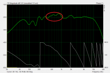
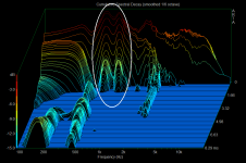
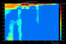
Secondly, I never really bothered to measure or dig into it but now I have, and I would like to get your opinions if these measurements reflect the sound impression I am getting. I have indicated the sections of the frequency range in the response and csd charts that I think are those resonances. Do you concur or disagree ?
Dayton Audio UA701CK Usher Speaker Kit Cherry 302-952
Parts Express DIY Project
These are place about 6" from the wall. I have always felt that the low-mid voice/speech range sounded a little bit boxy/honky, like some kind of a resonance artefact. First of all, I'd like to see if anyone who has heard these speakers share the same opinion or not ?
Secondly, I never really bothered to measure or dig into it but now I have, and I would like to get your opinions if these measurements reflect the sound impression I am getting. I have indicated the sections of the frequency range in the response and csd charts that I think are those resonances. Do you concur or disagree ?
Attachments
It's plausible. How's the panel damping and stuffing?
I would take a look at room placement. I'd be reluctant to modify the crossover. This peak is noticed by others it may be a necessary one. It's possible that firstly, your close wall placement is causing some issues in the lower midrange which might be helped by pulling them out a bit or moving them across, and secondly that your off-axis sound is causing colourations that may be helped by placement and toeing, or treatment.
I would take a look at room placement. I'd be reluctant to modify the crossover. This peak is noticed by others it may be a necessary one. It's possible that firstly, your close wall placement is causing some issues in the lower midrange which might be helped by pulling them out a bit or moving them across, and secondly that your off-axis sound is causing colourations that may be helped by placement and toeing, or treatment.
Not a comment on the drivers specifically, but the measurement technique.
If you're looking for resonances, don't use 1/3rd octave smoothing.
High Q resonances will be smoothed out and made ambiguous (or even invisible) by such coarse smoothing. Use the minimum amount of smoothing possible, in ARTA that means 1/24th octave for frequency response, and (from memory) 1/12th octave for CSD.
Also it's critical for CSD that the measurement is gated (a red finish marker is enabled) and that any room reflections are excluded from the gated period using this marker, otherwise the CSD will be invalid and will probably be showing room resonances and reflections as well as driver resonances. The long ridge just below 500Hz is an example of an invalid result caused by reflections entering the measurement. (For looking at resonances in a CSD you'll also want a wider amplitude scale - 25 or 30dB as 15dB will cut off too much information)
The same thing applies to the frequency response as well, if it's not a reflection free gated period you could be seeing room reflections in the response, it's not uncommon to see bumps in the midrange that are actually room reflections.
Trying to measure at 1Khz with enough frequency resolution to see resonances is quite challenging though, as it's difficult to get a sufficiently long reflection free gate time in a typical room.
I would put the speaker right near the middle of the room on a stand with the driver height half way between floor and ceiling and the microphone only about half a metre in front of the driver, then see how long you can get to the first reflection from the floor/ceiling, and take a gated but unsmoothed measurement.
Use the following calculator to help estimate the delay to first reflection if it's not obvious in the measurement impulse itself:
http://mehlau.net/audio/floorbounce/
(For example for a 2.4 metre high ceiling with the driver 1.2 metres off the floor and a 0.5 metre microphone distance the best you can do is 5.6ms)
Then you'll have the information you need to assess whether there is actually a driver resonance there.
Last edited:
Get modelling clay/Playdoh and cover inside walls, then put denim insulation or batting, etc. You may also want to play with stuffing a handfull of polyfil or equivalent. The acoustic foam provided in the kit never did much for me. I have a stellar 2-way with similar drivers (8948A and 9950) in the taller .75cu rectangular cabs and they disappear with the clay and denim insulation. They are also heavy as hell. Few hours work, but totally worth it.
Before going through the trouble of adding bracing or wall deadening material, I would simply add more layers of foam to the top and/or bottom, and the back wall. If that's the thinner PE egg crate, than a single layer is not enough for the back wall especially. I would do 3 layers there. If you don't have enough, I've used the high density 2" thick green foam blocks at Joann's and that stuff is very good. Every time I've ever had a boxy sound, adding more damping fixes the problem.
It is unlikely any amount of damping will fix the issue since the energy exciting the resonance is much more likely to be transmitted mechanically thru the box and not thru the airspace.
Wushuliu's technique will lower the panel frequency and make it lower Q -- both which in general make the resonance more likely to get excited and to be more likely to be heard. That he has practical experience saying it works means in this case it is workable.
Additional bracing will push panel resonances up so they are less likely to get excited.
dave
Wushuliu's technique will lower the panel frequency and make it lower Q
Why would it lower Q rather than just reduce amplitude?
Additional bracing will push panel resonances up so they are less likely to get excited.
Push resonance up to what frequency?
I'd agree with that. Panel damping and air space damping are two different and largely independent things.It is unlikely any amount of damping will fix the issue since the energy exciting the resonance is much more likely to be transmitted mechanically thru the box and not thru the airspace.
This is so often stated but is actually not true, and based on a misunderstanding of research into the audibility of resonances. Adding more damping to a mechanical resonance never makes it more audible, it makes it less audible.Wushuliu's technique will lower the panel frequency and make it lower Q -- both which in general make the resonance more likely to get excited and to be more likely to be heard.
The studies into the audibility of resonances that found lower Q resonances to be more audible were specifically comparing electronically created resonances where the different Q resonances were manipulated into having the same peak amplitude. (using a PEQ)
For example a 3dB resonant peak with a Q of 1 will be more audible than a 3dB peak with a Q of 2 because a wider bandwidth is affected. (A greater area under the curve...)
Mechanical resonances don't work this way though because adding damping simultaneously widens the response and lowers the amplitude of the peak.
You can't get a wider lower Q resonance with the same peak amplitude by just adding damping in a mechanical system. Different Q resonances always have different peak amplitudes.
It works out that as you add damping the peak amplitude drops more rapidly than the bandwidth increases and they become less audible.
Speaker dave posted a good reference for this issue in another thread some time ago (I could probably find it if I dug through my subscribed threads enough) which debunks the whole adding damping makes resonances more audible wives tale.
Less likely ? How so ?Additional bracing will push panel resonances up so they are less likely to get excited.
Subdividing a panel in half with a brace is not the same as a panel half as wide either.
If you put a solid brace half way across a panel you are not doubling the panel resonance frequency, you are actually suppressing the fundamental mode resonance of the panel, leaving the 2nd order mode panel resonance as the lowest panel resonance of significant amplitude.
It might seem that the panel resonance has been doubled in frequency but it hasn't, it's still a 2nd order mode resonance, where the panel flex (looked at from the edge) looks like a full sine-wave instead of half a sine-wave.
See the usual ugly spat developing at diyaudio here. Cabinet bracing...didn't we finish that topic?
Lets talk about that resonance. Doctor Joseph D'appolito clearly knows very little about designing speakers. Who is he anyway?
This design is clearly your typical boomy rear-reflex standmounter that is best put up on stands with rubber feet and kept away from walls. Our Troels did something similar with his "Studio 101" Proac 100 clone. A nearfield monitor for sure.
Studio 101 Monitorcopyright 2009 ©
Troels put a little notch at 800Hz on the scanspeak cut paper driver though. Higher crossover too. That's it really, isn't it?
Lets talk about that resonance. Doctor Joseph D'appolito clearly knows very little about designing speakers. Who is he anyway?
An externally hosted image should be here but it was not working when we last tested it.
This design is clearly your typical boomy rear-reflex standmounter that is best put up on stands with rubber feet and kept away from walls. Our Troels did something similar with his "Studio 101" Proac 100 clone. A nearfield monitor for sure.
Studio 101 Monitorcopyright 2009 ©
Troels put a little notch at 800Hz on the scanspeak cut paper driver though. Higher crossover too. That's it really, isn't it?
Had a quick look back and found the original post by speaker dave that I was thinking of regarding resonance audibility:Speaker dave posted a good reference for this issue in another thread some time ago (I could probably find it if I dug through my subscribed threads enough) which debunks the whole adding damping makes resonances more audible wives tale.
http://www.diyaudio.com/forums/mult...-better-material-enclosure-4.html#post2576881
Funnily enough I had forgotten it was planet10 he was responding to back then.
Doctor Joseph D'appolito clearly knows very little
about designing speakers. Who is he anyway?
Hi,
I assume there is some facetiousness involved in that comment
Usher seem to own the rights to using the good Doctors name
and of course in that context will use as much as they abuse it.
The actual design lacks baffle step compensation. So it needs
to be near walls. Fine for most AV fans. But near wall screws
up the lower midrange and always will and most don't care.
In my book it goes into a good AV speaker, not a good hifi speaker.
rgds, sreten.
The cab does have a vertical brace in it - http://www.parts-express.com/pdf/302-732s.pdf
and this is the foam -Acoustic Foam 1-1/2" x 24" x 18" UL 94 260-516
One thing I had noticed earlier was that the kit comes supplied with speaker caulk to be put around the drivers to isolate them from the baffle. But the pre-built version did not have it. No isolation. So I just grabbed some length of weather stripping I had lying around (not sure if that was a good choice or not) and put it around the drivers and mounted them again.
Can't agree with you there, sreten. There's HUGE bafflestep built into that crossover.
The Usher 8945A Woofer has Le of only 0.46mH. That's a standmounter.
I think it's broken and unfixable really. You are getting the usual 1kHz peak from the cabinet and driver. You can't really damp more with reflex. You can't put it near a wall because of the rear reflex. You can't notch without knowing the driver frequency response. Just gotta live with it.
An externally hosted image should be here but it was not working when we last tested it.
The Usher 8945A Woofer has Le of only 0.46mH. That's a standmounter.
I think it's broken and unfixable really. You are getting the usual 1kHz peak from the cabinet and driver. You can't really damp more with reflex. You can't put it near a wall because of the rear reflex. You can't notch without knowing the driver frequency response. Just gotta live with it.
You can't really damp more with reflex. You can't put it near a wall because of the rear reflex. You can't notch without knowing the driver frequency response. Just gotta live with it.
I disagree with that. That PE 1.5" egg crate is thin enough that you can definitely double it, even triple it. I would triple it on top (longest dimension) and double it in the back.
You could do some iterative listening. First just double top and back, then if still boxy sounding, triple top, finally triple back.
I've done this and the port output is not affected much. Just keep a clear path between port and woofer.
Another thought is you may have a strong port resonance, meaning there's a midrange peak at the port output. This can screw up the midrange as well. It's easy enough to place your ear near the port output to check for this. I've noticed I can reduce this resonance behavior by placing a brace between the woofer and port, so most of the port is not in a direct path from the woofer output. I've also placed a foam block around the port itself which seemed to reduce it. I'm not sure of the physics behind it though.
If none of that works to your satisfaction, then you may need to address panel resonances with bracing.
Less likely ? How so ?
THe big one is that the energy available to excite the resonance is inversly proportional to the square of the frequency althou it can be argued that this could approach the 4th order above some point.
A high Q resonance will also be less likely to be excited by music, since to get it going you have to pump energy into it continuously within its bandwidth.
A brace should never be placed at the centre of a panel to avoid the situation you describe.
dave
I gave up using egg carton foam twenty years ago. There may have been advances in foam since then but I don't much care. Still I agree with you that more damping material is worth trying.That PE 1.5" egg crate is thin enough that you can definitely double it, even triple it.
Addressing Planet10, a good wad of fibreglass may somewhat reduce the transmission of those higher frequencies to the panels making your suggestion workable, but on the issue of bracing I'll fall back on the recent discussions as Simon has highlighted.
You can't notch without knowing the driver frequency response. Just gotta live with it.
If we did the crossover from scratch, aiming to understand why the peaks in the middle are necessary or not, I think we'd find 2 simple limitations in this design. The limits of the system configuration, and those of the budget. I suspect it wouldn't take a week to max out and possibly reach the same conclusions as Dr D'Appolito. His supporting comments lead me to believe that he has done his best within the constraints, but has surely achieved more with other designs... but it may be mainly a matter of time and money to produce a better crossover.
I think it's broken and unfixable really. You are getting the usual 1kHz peak from the cabinet and driver. You can't really damp more with reflex.
Usual? I don't think damping material in a reflex box should be such an issue. Texts refer to box losses reducing the reflex action, maybe so, but this is a lower priority here I would think and I'd damp it as much as practical, as necessary, and/or as workable.
Last edited:
How do you figure that ? Whilst displacement drops with increasing frequency for the same SPL, peak acceleration stays the same, and it's the reaction force from the drivers acceleration directly feeding the panel that is the main source of panel vibration at least for the front panel, which is the one radiating towards the listener.THe big one is that the energy available to excite the resonance is inversly proportional to the square of the frequency althou it can be argued that this could approach the 4th order above some point.
All irrelevant though, because it's the ratio between the direct signal from the driver and the re-radiated signal from the resonating panel that determines its audibility. The panel might vibrate far less at high frequencies in terms of excursion, but so does the drivers cone so the ratio isn't changing just by pushing the frequency higher.
So the "less energy to excite resonances" is bogus. The excursion of both cone and panel vibrations are just less at higher frequencies, thats all.
Most music has a wide enough spectra to excite any resonances at least periodically if not continuously. A high Q resonance is audible as harshness, particularly at high frequencies, and results in a fatiguing listening experience. A low Q resonance is perceived as a simple tonal imbalance.A high Q resonance will also be less likely to be excited by music, since to get it going you have to pump energy into it continuously within its bandwidth.
A mechanical high Q resonance usually can't be corrected electronically because it's too unstable to be accurately targeted, while a low Q resonance is often easy to fix in the network or with EQ.
There is no time when a high Q mechanical resonance sounds preferable to a low Q resonance. It may not be excited in all music all the time, but when it is excited it is usually very obnoxious sounding.
It doesn't matter where you place the brace, you are suppressing different resonant modes to varying degrees, not simply pushing the resonant frequency up like stiffening the panel would.A brace should never be placed at the centre of a panel to avoid the situation you describe.
As I said, bracing a panel is not equivalent to stiffening the panel nor is it equivalent to multiple separate panels of the subdivided sizes, because the different parts of the panel are connected together. Your diagram above actually demonstrates this well as none of the above are fundamental modes, they're all 2nd order and higher modes as the brace has suppressed the fundamental.
Much like placing multiple subwoofers around a room can suppress certain modes without actually changing what the fundamental modes of the room are.
The reference you show there doesn't make a lot of sense as it only lists a single resonant frequency for each configuration, but any rectangular panel braced or unbraced will have different resonances in each axis.
dave
More likely they mean lowest measurable resonance not fundamental resonance, as when the box is subdivided in half the lowest measured resonance is not the fundamental resonance but the 2nd harmonic resonance.
Last edited:
So less energy leaves through the box walls at higher frequencies but this will still amount to the same level.THe big one is that the energy available to excite the resonance is inversly proportional to the square of the frequency
I think everyone knows that when a resonance is pushed it can cause extraneous noise or harmonics, be it creaking in the walls or simply a level dependent non-linearity in them as a medium, which could lead to the common misconception (IMO) that a certain amount of energy is needed to start a cabinet resonance, or that more energy makes them more loud/noticeable. Speaker Dave was refuting this as well if I remember correctly.
A high Q resonance may be harder to 'find', if this is what you are saying but a good speaker really doesn't leave many places for something like that to hide.A high Q resonance will also be less likely to be excited by music, since to get it going you have to pump energy into it continuously within its bandwidth.
Quite interesting to look at the basic cabinet dimensions internally.
400 H x 216 W x 270 D
Not your classic golden ratio cabinet (5x8x13) by any means. Doing the sums for speed of sound at 340 m/s, you get 850 Hz with a wavelength of 400 mm. Exactly right for a strong resonance on the height and width. You need some mass of wadding in the middle of the cabinet to fix that. Can't do it with reflex really.
Broken and unfixable. Eat that, Dr. D'Appolito!
- Status
- This old topic is closed. If you want to reopen this topic, contact a moderator using the "Report Post" button.
- Home
- Loudspeakers
- Multi-Way
- Usher 701 resonance issues ?