In an attemp to sort out if there is anything good about followers from the booooring Ju-thread I modelled three versions of a typical SE triode-amp.
Any ideas what came out ouf this wrt uneven order harmonics and THD? It anyway indicates to follow only one route......
I actually also modelled three MJK-style parafeeds with Schaded 6L6 with unexpected results, but that will be saved for later.
Any ideas what came out ouf this wrt uneven order harmonics and THD? It anyway indicates to follow only one route......
I actually also modelled three MJK-style parafeeds with Schaded 6L6 with unexpected results, but that will be saved for later.
Attachments
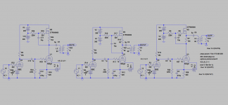
With the first circuit you will see the distortion of the output valve, loaded by the OPT-transformed load. The third circuit will largely give you the distortion of the 'follower'. The second circuit will be somewhere between. The actual distortion levels depend on active device types and bias points as much as architecture, so difficult to say more than that.
DF, can tell you the second will not even be close to "somewhere in between".
Don, Michael, kenpeter and a few others have explained this briefly before. Triode-antitriode behaviour seems to be no gimmick.
Don´t mind the possible refinements possible of the circuit. This is just a runofthemill design made for comparision use.
I already know the predictions. But to some it will be surprising to know their indicated behaviour.
One thing for sure though, even if the follower looks right to some it is the one to be avoided due to the highest uneven harmonics of them all.
Last edited:
1st circuit a CCS loaded triode. Probably the worst distortion.
The 2nd (anti-triode version) should ideally have a little more resistance in the bottom 82 Ohm resistor to provide for the Mosfet drive signal component.
This then centers the dynamic range too. I think this should have the 2nd lowest distortion if set up optimally, since it 2X's the load Z on the triode.
The 3rd circuit I presume is supposed to be a Mu follower? The Mu-F normally has a high resistance up top the bottom tube plate.
As actually set up, the high gm Mosfet probably drives the load with next to no distortion and still lets the triode below it run with nearly no load, for minimal distortion of them all.
SRPP model?
Last edited:
The 3rd circuit has the greatest assymmetry of current drive, so likely has the higher odd harmonics. Putting the usual high value resistor above its plate for a typical Mu follower would likely reduce its power output capability way below the other circuits.
On second thought, the 3rd circuit is still putting a 164 Ohm load onto the tube, since it still has to develop the drive signal for the Mosfet. So I'm demoting its standing to 2nd or 3rd worst distortion.
Anti-triode takes the lead.
On second thought, the 3rd circuit is still putting a 164 Ohm load onto the tube, since it still has to develop the drive signal for the Mosfet. So I'm demoting its standing to 2nd or 3rd worst distortion.
Anti-triode takes the lead.
Last edited:
Ah, but the 164 Ohms is bootstrapped. Looks like the tube sees (164 gm Rl) for its load. So maybe about 10 Rl load (10 x load), which is the lightest load of the three, so it (3rd circuit) stays as the lowest distortion. Anti-triode as 2nd (with 2x load) and CCS+load (1x load) as worst dist.
If you put a triode or pentode up top though, the (164 gm Rl) factor will drop to more like (1 x load). Its the high Mosfet gm that is making the big deal there.
OK, I give up, whats the answer?
If you put a triode or pentode up top though, the (164 gm Rl) factor will drop to more like (1 x load). Its the high Mosfet gm that is making the big deal there.
OK, I give up, whats the answer?
Last edited:
Hey Don,
You have already found out. Used the "gyrator-style" to have it work on top of pentodes too. But these are the predictions/indications:
THD:
1 G
2 F 1,2x higher than G
3 AT, 1,3x higher than G
Uneven:
1 AT
2 G 3rd H 2,5x higher than AT
3 F 3rd H 7x higher than AT
The higher harmonics where all a lot better for the AT.
In other words: Stay away from the follower!
Going for the MJK-style 6L6/depl.fet-hybrid, both the F and AT where odd-order killers compared to G. AT just marginally better though.
For the A-T, try adjusting the bottom 82 Ohm resistor higher (or the ratio of bottom to top 82R). This needs to be slightly higher to supply the drive signal for the Mosfet (for finite gm). Broskie's SRPP+ writeup gives the design rules, but since the Mosfet gm varies with current like tubes, easier to just tweek the R ratio till the odd Harmonics minimize. At some R the odd harmonics should largely null out since it will be closest to P-P, but it will still have the odd harmonics from the tube, since A-T preserves them.
SRPP+ (tube up top instead) should be able to largely null out the odd harmonics, with matched gm top and bottom, like normal P-P. (will need a much bigger 82R/82R ratio for the tube drive though)
-------
The 3rd circuit, the Mosfet follower, should be doing the best performance, since it nearly completely unloads the tube, which becomes just the driver stage for it. (as long as it has a high gm Mosfet for the follower)
The A-T reduces the loading on the tube by 2x (its just a 2x impedance converter circuit), and the gyrator is stuck at 1x. So I would expect the A-T to have lower harmonics in general versus the gyrator. (Assumes that the Mosfet gate capacitance does not get in the way though. That STP8NM60 is an awfully big Mosfet. Have a spice model for an FQP1N60 ?)
Last edited:
What's the OPT turns ratio? I.e. what's the OPT primary impedance. I don't see it anywhere.
The AT circuit should produce the same spectrum as the gyrator only if the AT is loaded by 1/2 the OPT primary impedance vs. the gyrator, and the resistor ratio tweaked a little to compensate for the finite gfs of the MOSFET. This would make the load line the same as the gyrator case.
I don't know much about the big MOSFETS except that they're barely turning on at 100 mA and may not be in a good part of their gfs curve for this. I use a 2N60. The DN2540 is pretty linear in the 10-100 mA range.
How much cancellation is going on between the stages?
Are you planning to post the actual results and measurement conditions?
Thanks,
Michael
Last edited:
Hey Don and Michael,
We know AT with PP works after me building the 6B4G/6P3S SEPTOR and you having built other prototypes with MOSFETs as the AT.
The SEPTOR have also been tried with MOSFET instead of 6P3S and showed even better results.
So, always high Gm devices at the AT side in the PP designs. The lower the Gm the higher the distortion. This probably goes for the SE follower being mu or AT.
Hey Lars,
Now I'm not sure exactly what you tested and what the results are.
Did you test with both tubes and MOSFETS as the top devices? And with tubes you had some harmonic cancellation? But the MOSFET "works"?
I think I'm more confused than ever. Can you present the results with their circuits?
Thanks!
Michael
Hey Michael,
?? now its my turn to be confused") .
.
My last post didn´t concern the parafeed. It was about the poweramps built a few years ago in PP configuration, not follower. You did some prototype with triode+DN2540 and I did the SEPTOR in another thread.
Only the last sentence was about the follower.
I am trying to start a theoretical discussion here, nothing else.
?? now its my turn to be confused
. My last post didn´t concern the parafeed. It was about the poweramps built a few years ago in PP configuration, not follower. You did some prototype with triode+DN2540 and I did the SEPTOR in another thread.
Only the last sentence was about the follower.
I am trying to start a theoretical discussion here, nothing else.
Just remember we had all this covered before:
http://www.diyaudio.com/forums/tubes-valves/128950-spud-assist-totem-pole-current-mirror-pp-hybrid.html
Still using the highest possible GFs/Gm device on top, seem to minimize odd order harmonics.
http://www.diyaudio.com/forums/tubes-valves/128950-spud-assist-totem-pole-current-mirror-pp-hybrid.html
Still using the highest possible GFs/Gm device on top, seem to minimize odd order harmonics.
Corrected the errors and indications are AT will have the highest odd order harmonics. About the hybrid sims that where correct, AT seems still marginally better.
I guess I don't understand this statement and wondered if you were going to show the plots to illustrate.
- Status
- This old topic is closed. If you want to reopen this topic, contact a moderator using the "Report Post" button.
- Home
- Amplifiers
- Tubes / Valves
- Why a follower in a parafeed triodeamp?