I plan to build the phono stage pre-amp based on the below schematic:
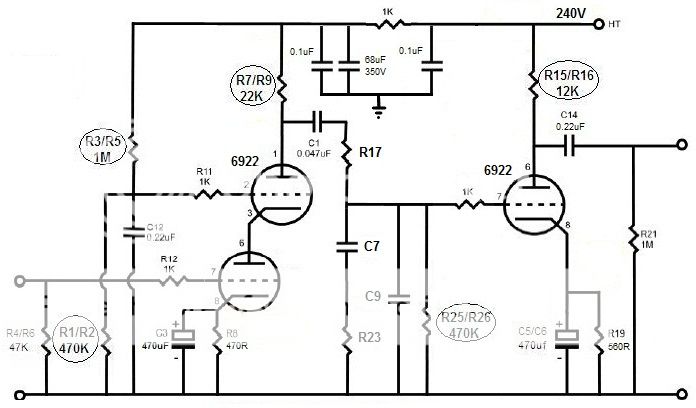
I use this link to calculate the values of RIAA components by choosing the value of R1 (i.e. R17 in the schematic) at 68K in order to get the values of the other RIAA components close to standard values:
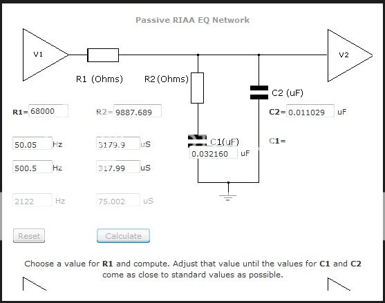
I also note from the link that the driving tube V1 should have a low enough output impedance relative to R1 and that the following tube V2 should have an input impedance of at least 50 times R1 to prevent loading.
So my question is if my chosen value of R1 of 68K is appropriate in this application or which value of R1 I should choose for this application.
Thanks and regards
Andersen
I use this link to calculate the values of RIAA components by choosing the value of R1 (i.e. R17 in the schematic) at 68K in order to get the values of the other RIAA components close to standard values:
I also note from the link that the driving tube V1 should have a low enough output impedance relative to R1 and that the following tube V2 should have an input impedance of at least 50 times R1 to prevent loading.
So my question is if my chosen value of R1 of 68K is appropriate in this application or which value of R1 I should choose for this application.
Thanks and regards
Andersen
Are you aware the input stage is a cascode? If so you should know Zout is in the ballpark of R7. So your values are way off. This means, if you go for R17=68k you should use 68k+22k=90k as R1 in the link.
Still you will only get ballpark figures. You must use a rev-RIAA (Hagerman) to get it right.
Still you will only get ballpark figures. You must use a rev-RIAA (Hagerman) to get it right.
Many thanks, Lars for your response. But I don't really think that R1=68K+22K as I did check some schematics with this calculators and the results are accurate. Anyway, my concern is how high or low the value of R17 should be in this specific case of 6922 cascode with Ra of 22K?
Thanks and regards
Thanks and regards
You should pay attention to Lars, he is absolutely correct.
If you want to use values close to those based on your original understanding change R17 to 47K, this should put you in the ballpark allowing for the cascode source impedance to be slightly lower than the plate load resistor of 22K. (The cascode will look like an rp of up to several hundred K ohms or so in parallel with the 22K plate resistor.) You have to take this into account in the selection of R17. I've designed a number of cascodes as well as conventional RIAA stages with this RIAA network. (First analyzed in detail by Stanley Lipshitz, University of Waterloo some 3 or more decades ago)
An inverse RIAA network is not strictly necessary, but you do need to know what the response is supposed to be at any given frequency and have a good way to precisely measure it. Expect to tweak values, particularly R17 to get it close. Don't neglect the miller capacitance in the second stage either if you want accurate HF response.
Note that the assumption made in all of these calculators is that V1 has a source impedance of 0 ohms, (usually an op-amp) your cascode does not and its source impedance is effectively part of R17.
Noted with thanks. Can you all please kindly help me determine the values of the RIAA components: R17, R23, C7, C9 to complete the schematic?
Thanks and regards
Andersen
See the above post. Try 47K for R17 with the existing values if you have them - otherwise I would recommend slightly higher effective resistor value for R17 in order to reduce the effect of variations in cascode source impedance due to aging (reduction of transconductance) in the cascode stage.
I'd aim for something in the 110K range total so say R17 = 88.7K + ~21K (cascode) for the basis of the calculations. This should be better for linearity in the cascode as well.
You can take R25/R26 in account by assuming they are in parallel with R17, and that R17 is, as said, the sum of the 'real' R17 + (Ra // Rp).
Then just use the online calculator.
And be prepared to tweak.
jan didden
Or place R25/R26 before R17 as I do which gets rid of the implicit voltage divider in the network. (I was remiss for not mentioning this sooner.) Make sure the sum of R25/R26 and R17 does not exceed the maximum recommended grid circuit resistance of the 6922. Should be safe with 301K for R25/R26. C1 should be much larger to assure good response down to 20Hz.. I'd recommend at least 0.1uF.. (roughly -3dB @ 5Hz, -1dB @ 10Hz)
Many thanks, Kevin. I will try your 110K recommendation. So in order to get the values of other RIAA components I will apply R1 at 110K in the calculator, right?
Yes, that's correct. Just remember to move R25/25 after C1 and before R17. Be prepared to do some tweaking to compensate for component tolerances and small variances from predicted circuit performance.
Usually what I do is go down to the next closest standard 1% resistor value and pad it up to the target value. (Then adjust by measurement if necessary) Try to purchase the caps from someone who can measure and select parts that closely match your target values. If you done really well usually all you will need to tweak is the value of R17.
Do not forget to take into account the approximate miller capacitance of the second stage as it is significant. Say it is 50pF then you would want a value that is 50pF less than the calculated value. Paralleling a few selected caps to get to the right overall value is a time honored technique. If you can get them polystyrene foil caps are excellent for EQ.
Consider infra-red or red leds for cathode bias (now really fixed bias) as opposed to RC based bias, good performing electrolytics at these low signal voltages can be hard to find.
6DJ8 has a mu of 33, with a 12K plate load and assuming >100K in the next stage you might achieve a gain of perhaps 26 (28.3dB) miller capacitance is about 1.2pF, so 26 x 1.2 =31.2pF, plus about 10pF for inter-electrode capacitance between grid, cathode, shield, and cathode to plate.. So figure roughly 42pF from this source, round off to 50pF for convenience and because there are likely external strays as well. Not a big contributor overall.
Getting the right values is almost impossible for a number of reasons when using any easy calculator. I've tried virtually all methods up to very complicated spreadsheets to calculate RIAA EQ values.
There is only one way, IMHO, to calculate it accurately and that is a SPICE sim. LTSPICE is free. Check out Intact Audio forum to get models and info on how to use.
In the end, it will save you so much time and effort that you will wonder how you got on without it. All the other guess work and assumptions will become just that.
cheers,
Stephen
I'm a big fan of LTSpice and have been using it for about 8 years now, but I have also had no problem in the past calculating the correct values using first principles and Stanley Lipshitz's useful equations which are probably the basis of most of those online calculators.
Also spice is only as accurate as the tube models used to build the simulation.. Note that there is plenty here as well about modeling tube circuitry in LTSpice.
Twenty four years ago when I designed my first phono stage early versions of spice were only available at few universities, but I managed to design and build a passively equalized phono pre-amp that required only very minimal tweaking to one resistor value. I admit at the time I was aiming for accuracy of about +/-0.5dB as I was not really able to measure to a much greater accuracy level, and getting tight precision parts before the internet was difficult.
Ultimately no matter how you arrive at a (good) design the passive components are going to be the let down. Careful selection and trimming may be required not because of a design issue but because of the parts themselves.
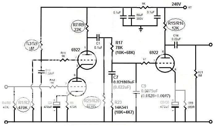
I've just modified the schematic as below based on your recommendations/comments except for the value of R17 which I chose at 78K falling in the range of 100K (78K+22K) in order to get the values of other RIAA components close to standard values. Is it acceptable?
BTW, is it ok if I use a 100K volume pot at the position of R17 (keeping the other RIAA components' values remained) and adjust the volume pot 'till getting the best result?
Thanks and regards
Andersen
An externally hosted image should be here but it was not working when we last tested it.
BTW, is it ok if I use a 100K volume pot at the position of R17 (keeping the other RIAA components' values remained) and adjust the volume pot 'till getting the best result?
Thanks and regards
Andersen
Last edited:
Kevin, in order to get the values of other RIAA components by using the calculator I posted, the value of R1 should be the value of (R17+Zo)//R25, is it correct?
Taking my schematic as an example, the value of R1 should be (78K + 22K)//470K equal to 82K456?
No, moving R25 ahead of the network removes it from the network equation - I would purchase 76.8K plus 499, 1.21K, and 1.69K. The 76.8K is permanently installed, start with 1.21K in series with it, if too bright change to 1.69K, if too dull 499 - this is basic trimming.. Range could be potentially greater than my suggested values. Best to measure if you have the means. You should not trust your ears for this task.
Do you have a meter, scope and generator? Good soundcard in your PC?
Ok, I see. So my statement is only right if R25 stays in its original position, right? What types of resistors and capacitors would you recommend me?No, moving R25 ahead of the network removes it from the network equation - I would purchase 76.8K plus 499, 1.21K, and 1.69K. The 76.8K is permanently installed, start with 1.21K in series with it, if too bright change to 1.69K, if too dull 499 - this is basic trimming.. Range could be potentially greater than my suggested values. Best to measure if you have the means. You should not trust your ears for this task.
Do you have a meter, scope and generator? Good soundcard in your PC?
I don't have those equipments/tools but will find a store to have it measured properly.
Thanks and regards
Andersen
I'd recommend good 1% tolerance 1/2W (RN60) metal films like Dale or PRP (Precision Resistive Products), for the eq caps polystyrene film and foil caps like the REL RT series. For coupling and bypass capacitors Russian FT-3 series comes to mind. Output cap probably a good polypropylene like the Clarity SA/ESA series or something from Janszen.. There are many choices, these are just some that have worked for me in the past, none are too expensive.
Alternately you could order parts from Michael Percy, and have them shipped to Vietnam by mail.. I've bought small quantities of parts from him for more than 24yrs now - highly recommended. Here: Michael Percy Audio Ordering Information Not sure about duty and the like however.
Alternately you could order parts from Michael Percy, and have them shipped to Vietnam by mail.. I've bought small quantities of parts from him for more than 24yrs now - highly recommended. Here: Michael Percy Audio Ordering Information Not sure about duty and the like however.
- Status
- This old topic is closed. If you want to reopen this topic, contact a moderator using the "Report Post" button.
- Home
- Amplifiers
- Tubes / Valves
- Need help on RIAA